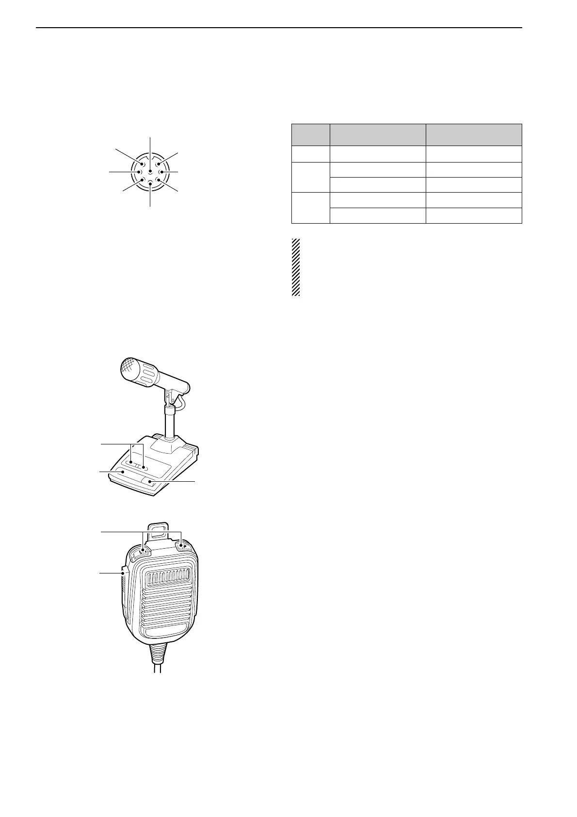
■ Microphone connector information
(Front panel view)
CAUTION: DO NOT short pin 2 to ground as this
can damage the internal 8 V regulator.
NOTE: DC voltage is applied to pin 1 for micro-
phone operation. Use caution when using a non-
Icom microphone.
■ Microphones (options)
q UP/DOWN SWITCHES [UP]/[DN]
Change the selected readout frequency or memory
channel.
• Continuous pushing changes the frequency or memory
channel number continuously.
• While pushing [XFC], the transmit readout frequency can
be controlled while in split frequency operation.
• The [UP]/[DN] switch can simulate a key paddle. Preset
in the keyer set mode. (p. 4-12)
w PTT SWITCH
Push and hold to transmit; release to receive.
e PTT LOCK SWITCH (available for SM-20 only)
Push to toggle between transmit and receive.
2-10
2
INSTALLATION AND CONNECTIONS
[MIC]
FUNCTION DESCRIPTION
Pin No.
w +8 V DC output Max. 10 mA
e
Frequency up Ground
Frequency down Ground through 470 Ω
r
Squelch open “Low” level
Squelch closed “High” level

 Loading...


