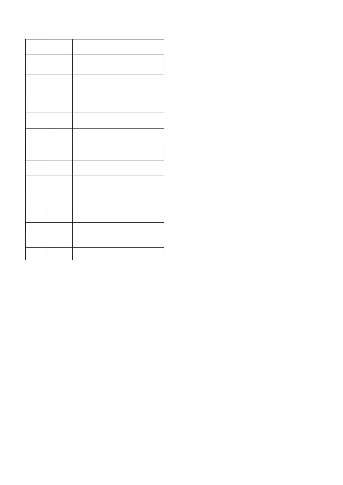
4 - 9
Pin Port
Description
number name
84
85
86
88–90
92
94–96
97
98
99–127
128–131
138
139
141
144
50M
CTSEL
DTCS
SEG37–
SEG35
SEG34
SEG33–
SEG31
CONT1
CONT0
SEG28–
SEG0
COM3–
COM0
VOLC
CTCOUT
BEEP
WXALT
Outputs the 50 MHz modulation circuit
control signal.
Low: While 50 MHz is transmitting.
Outputs the CT3 switch (LOGIC unit;
Q301) control signal.
Low: DTCS/CTCSS is selected.
Outputs the DTCS decorder filter con-
trol signal.
Output segment data to the LCD
(LOGIC unit; DS4, pins 5–7).
Outputs segment data to the LCD
(LOGIC unit; DS4, pin 8).
Output segment data to the LCD
(LOGIC unit; DS4, pins 9–11).
Output the LCD contrast control sig-
nals.
Output segment data to the LCD
(LOGIC unit; DS4, pins 12–40).
Output common data to the LCD
(LOGIC unit; DS4, pins 1–4).
Outputs the volume IC (AF unit;
IC251, pin 5) control signal.
Outputs CTCSS/DTCS signals.
Output beep, DTMF tone, 1750 Hz
tone sounds.
Input port for the WX alert signal.
4-5-3 CPU (Continued)