EasyManua.ls Logo

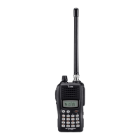
Icom IC-E92D Service Manual

Icom IC-E92D
60 pages
To Next Page IconTo Next Page
Page #1 background imageLoading...
Page #1 background image
S-14416XZ-C1
Jan. 2008
VHF/UHF DIGITAL TRANSCEIVER

Other manuals for Icom IC-E92D

Questions and Answers:

Icom IC-E92D Specifications

General IconGeneral
TypeHandheld Transceiver
Battery LifeApprox. 10 hours
Waterproof RatingIPX7
ModulationFM
Battery7.4 V DC
FeaturesD-STAR, GPS

Summary

INTRODUCTION

CAUTIONS AND SAFETY

ORDERING REPLACEMENT PARTS

REPAIR GUIDELINES

SECTION 1 SPECIFICATIONS

GENERAL SPECIFICATIONS

Covers frequency, mode, memory, temp range, power, current drain, and digital/voice coding.

RECEIVER SPECIFICATIONS

Details receiver sensitivity, selectivity, system, audio output, and squelch sensitivity.

TRANSMITTER SPECIFICATIONS

Outlines transmitter power, frequency deviation, spurious emissions, and mic impedance.

SECTION 2 INSIDE VIEWS

LOGIC UNIT COMPONENTS

Identifies key components on the logic unit board.

MAIN UNIT COMPONENTS

Identifies key components on the main unit board.

RF UNIT COMPONENTS

Identifies key components on the RF unit board.

SECTION 3 DISASSEMBLY INSTRUCTION

SECTION 4 CIRCUIT DESCRIPTION

4-1 RECEIVER CIRCUITS

Explains the signal path for incoming radio frequencies across various bands.

4-2 TRANSMITTER CIRCUITS

Describes the audio and RF signal paths for transmitting.

4-3 FREQUENCY SYNTHESIZER CIRCUITS

Details the VCO and PLL circuitry for frequency generation.

4-4 CPU PORT ALLOCATION

Maps CPU pins to specific functions and signals.

4-5 VOLTAGE DIAGRAMS

Illustrates power distribution across the unit.

SECTION 5 ADJUSTMENT PROCEDURES

5-1 PREPARATION

Lists required instruments and setup for adjustments.

5-2 TRANSMIT AMPLIFIER ADJUSTMENT

Covers calibration of transmit power and current.

5-3 FREQUENCY ADJUSTMENT

Details the procedure for calibrating the radio's frequency.

5-4 DEVIATION ADJUSTMENTS

Explains how to set FM, DV, and tone signal deviations.

5-5 RECEIVE ADJUSTMENTS

Covers calibration for receiver sensitivity and S-meter.

SECTION 6 PARTS LIST

SECTION 7 MECHANICAL PARTS

CHASSIS PARTS

Lists chassis parts and optional accessories.

UNIT MECHANICAL PARTS

Details mechanical parts for main, RF, VCO, and logic units.

SECTION 8 BOARD LAYOUTS

LOGIC UNIT BOARD LAYOUT

Visual guide to component placement on the logic board.

MAIN AND RF UNIT BOARD LAYOUTS

Visual guides for main and RF unit component placement.

VCO UNIT BOARD LAYOUT

Visual guide to component placement on the VCO board.

SECTION 9 BLOCK DIAGRAM

CHASSIS AND LOGIC UNIT BLOCK DIAGRAMS

Shows functional blocks within the chassis and logic units.

MAIN AND RF UNIT BLOCK DIAGRAMS

Illustrates signal flow in main and RF units.

VCO UNIT BLOCK DIAGRAM

Depicts functional blocks of the VCO unit.

SECTION 10 VOLTAGE DIAGRAM

LOGIC UNIT VOLTAGE DIAGRAM

Shows voltage levels and distribution for the logic unit.

Related product manuals