5 - 1
SECTION 5 ADJUSTMENT PROCEDURE
5-1 PREPARATION
¤ REQUIRED INSTRUMENTS
INSTRUMENTS SPECIFICATION INSTRUMENTS SPECIFICATION
DC Cable OPC-254L (Optional product) JIG cable
(See the illust below)
Power Supply
Output voltages : 5.0–13.5 V DC
Current capacity : More than 3 A
Multimeter
Input impedance : 50 k
Ω
Measuring range : 0.1–10V/0.01–5 A
RF Power Meter
(terminated type)
Measuring range : 0.1–10 W
Frequency range : 100–500 MHz
Impedance : 50
Ω
SWR : Less than 1.2 : 1
Standard Signal
Generator (SSG)
Frequency range : 0.1–1000 MHz
Output level : 0.04 µV to 32 mV
(–28 dBu to 90 dBu)
Frequency Counter
Frequency range : 0.1–600 MHz
Frequency accuracy : ±1 ppm or better
Input level : Less than 1 mW
AC Millivoltmeter Measuring range : 10 mV to 10 V
Attenuator
Power attenuation : 30 dB
Capacity : More than 10 W
Modulation
Analyzer
Frequency range : 30–600 MHz
Measuring range : 0 to ±10 kHz
Audio Generator
Frequency range : 300–3000 Hz
Output level : 1–500 mV
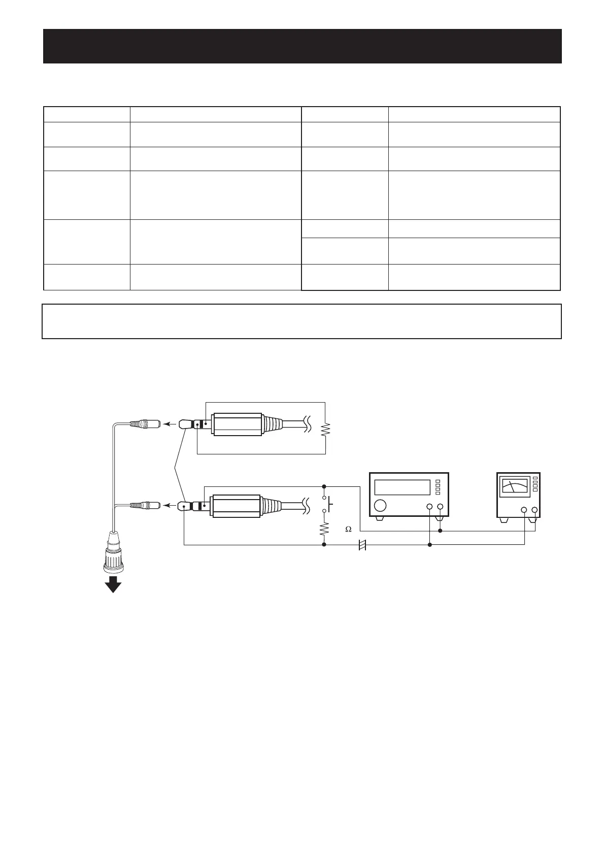
¤ JIG CABLE CONNECTION
CAUTION!: BACK UP originally programmed contents (Memory channels, Common settings, etc.) in the transceiver using optional
RS-92
REMOTE CONTROL SOFTWARE before starting adjustment.
When all adjustments are completed, these contents in the transceiver will be cleared.
OPC-1797
(Optional product)
3-conductor 2.5 (d) mm
[MIC]
To the [DATA/MIC/SP] jack
JIG cables
[SP]
plug
(MIC)
(GND)
33 k
+−
AC
MILLIVOLTMETER
(10 mV to 10 V)
AUDIO GENERATOR
(300–3000 Hz/1–500 mV)
+−
PTT
+
4.7 µF
3-conductor 3.5 (d) mm plug
(CLONE)
(GND)
1 kΩ
(4
#(/
5.1