5-4 DEVIATION ADJUSTMENTS
Select an adjustment item using [2]
/ [8] keys, then set the adjustment value as specifi ed using [DIAL].
ADJUSTMENT ADJUSTMENT CONDITION OPERATION
ADJUSTMENT
ITEM
VALUE
FM DEVIATION
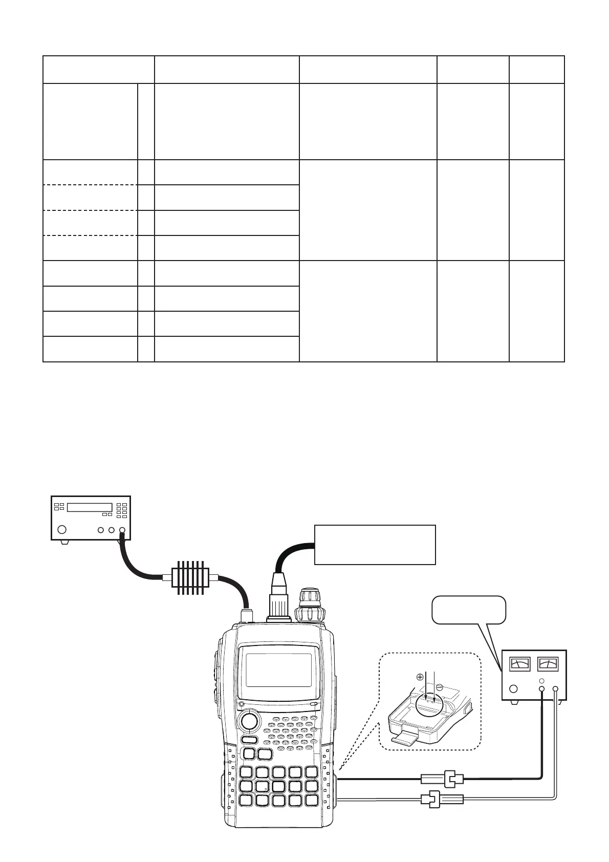
[PREPARATION]
0 • Supply voltage : 7.4 V 1) Connect a Modulation
Analyzer to the antenna
connector through an
Attenuator.
2) Connect an Audio Generator
to the JIG cable (see the
page 5-1).
––
(@1 kHz)
[VHF (BAND LOW)]
1 • Displayed freq. : "
"
• Transmitting
1) Set the Audio Generator as;
Frequency : 1 kHz
Level : 90 mVrms
2) Adjust the deviation using
[DIAL], then release the PTT
and push [BAND] to store the
adjustment value.
[
(/8
] 4.2–4.3 kHz
[VHF (BAND HIGH)] 2 • Displayed freq. : "
"
• Transmitting
[UHF (BAND LOW)] 3 • Displayed freq. : "
"
• Transmitting
[UHF (BAND HIGH)] 4 • Displayed freq. : "
"
• Transmitting
(@300 Hz)
[VHF (BAND LOW)]
5 • Channel : "
"
• Transmitting
1) Set the Audio Generator as;
Frequency : 300 Hz
Level : 90 mVrms
2) Adjust the deviation using
[DIAL], then release the PTT
and push [BAND] to store the
adjustment value.
[
(/4
] 4.0–4.1 kHz
[VHF (BAND HIGH)] 6 • Displayed freq. : "
"
• Transmitting
[UHF (BAND LOW)] 7 • Displayed freq. : "
"
• Transmitting
[UHF (BAND HIGH)] 8 • Displayed freq. : "
"
• Transmitting
5 - 11
MODULATION ANALYZER
(0.1–500 MHz)
SETTING
HPF : OFF
LPF : 20 kHz
De-emphasis : OFF
Detector : (P-P)/2
ATTENUATOR
(30 dB/10 W)
JIG cable
(See the page 5-1)
(4
#(/
5.1
7.4 V
Fusese
(3A)
DC power supply
⊕
−
–
+
Be sure the polarity.
To the battery contact pins