5 - 14
5-5 RECEIVE ADJUSTMENTS
P
WHOLE PROCEDURE OF RECEIVE ADJUSTMENTS
1) Select an adjustment item using [2]
/ [8] keys.
2) Set the SSG as specifi ed (frequency, deviation and output level).
3) Push the [BAND] key to adjust (automatic) and store the adjustment value.
ADJUSTMENT ADJUSTMENT CONDITION OPERATION
ADJUSTMENT
ITEM
VALUE
A BAND
RECEIVE
SENSITIVITY
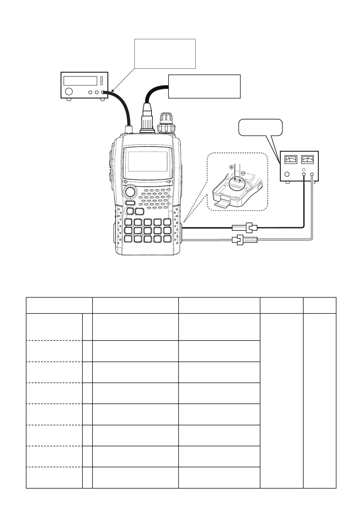
[PREPARATION]
0 • Supply voltage : 7.4 V • Connect an SSG to the
antenna connector and set as;
Modulation : 1 kHz
Deviation : 3.5 kHz
[
6T#
]
Push the
[BAND] key.
(Automatic
adjustment)
[30.1 MHz] 1 • Displayed freq. : "
"
• Receiving
• Set the SSG as;
Frequency : 30.1 MHz
Level : 0 dBµ
[49.9 MHz] 2 • Displayed freq. : "
"
• Receiving
• Set the SSG as;
Frequency : 49.9 MHz
Level : 0 dBµ
[50.1 MHz] 3 • Displayed freq. : "
"
• Receiving
• Set the SSG as;
Frequency : 50.1 MHz
Level : 0 dBµ
[75.9 MHz] 4 • Displayed freq. : "
"
• Receiving
• Set the SSG as;
Frequency : 75.9 MHz
Level : 0 dBµ
[76.1 MHz] 5 • Displayed freq. : "
"
• Receiving
• Set the SSG as;
Frequency : 76.1 MHz
Level : 0 dBµ
[90.2 MHz] 6 • Displayed freq. : "
"
• Receiving
• Set the SSG as;
Frequency : 90.2 MHz
Level : 0 dBµ
[117.9 MHz] 7 • Displayed freq. : "
"
• Receiving
• Set the SSG as;
Frequency : 117.9 MHz
Level : 0 dBµ
STANDARD SIGNAL GENERATOR
(0.1–1000 MHz)
CAUTION:
DO NOT transmit while
an SSG is connected to
the antenna connector.
JIG cable
(See the page 5-1)
(4
#(/
5.1
7.4 V
Fusese
(3A)
DC power supply
⊕
−
–
+
Be sure the polarity.
To the battery contact pins