5 - 14
ADJUSTMENT MODE ADJUSTMENTS (Continued)
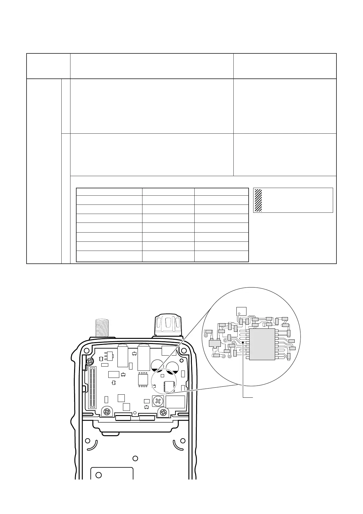
The following adjustment must be performed at “ADJUSTMENT MODE”.
S-METER
ADJUSTMENT ADJUSTMENT CONDITION OPERATION
1
2
• Displayed frequency :
(SM ch.) 1.620 MHz B
• Mode : FM
• Connect the SSG to the antenna connector and set as:
Level : 0.63 µV* (–111 dBm)
Modulation : 1 kHz
Deviation : ±3.5 kHz
• Receiving
• Same operation as step 1 for the listed frequencies and SSG
level shown below.
• Some adjustment frequencies must adjust both FM and WFM
modes.
When adjust the WFM mode, set the SSG’s deviation as
±52.5 kHz.
Push the [BAND] key.
Push the [BAND] key.
*This output level of the standard signal generator (SSG) is indicated as SSG’s open circuit.
• AF UNIT
ADJUSTMENT freq.
(SM Ch.) 28.100 MHz
B
(SM Ch.) 51.000 MHz
(SM Ch.) 145.100 MHz
A
(SM Ch.) 180.100 MHz
A
(SM Ch.) 435.100 MHz
(SM Ch.) 520.100 MHz
A
(SM Ch.) 729.100 MHz
A
SSG level (FM)
0.5 µV (–113 dBm)
0.5 µV (–113 dBm)
0.5 µV (–113 dBm)
0.63 µV (–111 dBm)
0.5 µV (–113 dBm)
0.79 µV (–109 dBm)
0.5 µV (–113 dBm)
SSG level (WFM)
–
1.8 µV (–102 dBm)
1.8 µV (–102 dBm)
3.2 µV (– 97 dBm)
–
3.2 µV (– 97 dBm)
3.2 µV (– 97 dBm)
S-METER ADJUSTMENT FREQUENCY LIST
NOTE:
A: [EUR], [ITR], [UK] only
B: except [ESP]