EasyManuals Logo

Icom IC-F1610 Instruction Manual

Icom IC-F1610
22 pages
To Next Page IconTo Next Page
To Previous Page IconTo Previous Page
Page #16 background imageLoading...
Page #16 background image
12
3
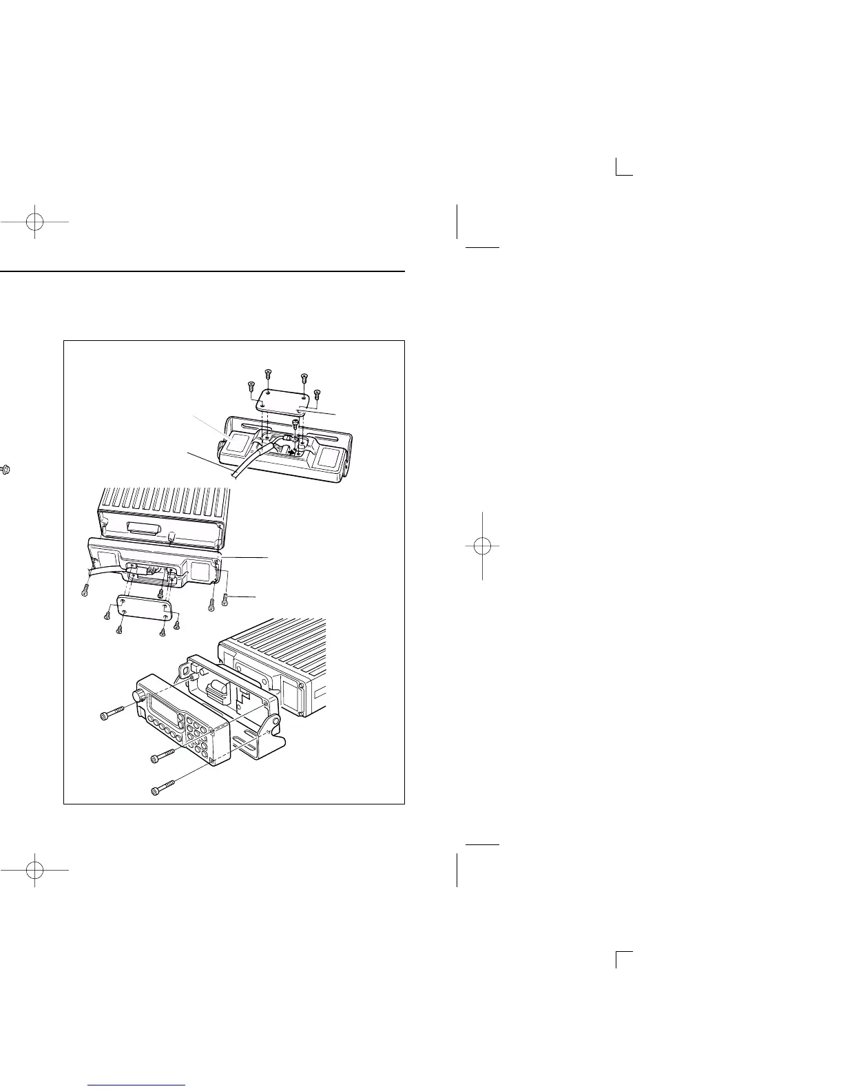
CONNECTION AND INSTALLATION
Separation (using RMK-1)
Mounting
Separation
Separate the front panel from the transceiver main unit
using the allen wrench (
1
32).
Connect the optional OPC-609 cable to both the front and
main unit attachments (gures 1 and 2).
Remove the rear plate of the attachment.
Use the supplied screw to connect a cable lug.
For the main unit attachment, attach to the main unit using the
supplied screws, in advance.
Attach the front panel and attachment with the 3 removed
allen socket bolts (g. 3).
When using
self-tapping screws
Spring washer
Flat washer
Fig. 3
Fig. 1
Fig. 2
OPC-609
Attachment
(for front panel)
Attachment
(for main unit )
Rear plate
Supplied screws
with the RMK-1
IC-F1610_F2610.qxd 03.3.7 16:29 Page 12 (1,1)

Other manuals for Icom IC-F1610

Questions and Answers:

Question and Answer IconNeed help?

Do you have a question about the Icom IC-F1610 and is the answer not in the manual?

Icom IC-F1610 Specifications

General IconGeneral
BrandIcom
ModelIC-F1610
CategoryTransceiver
LanguageEnglish

Related product manuals