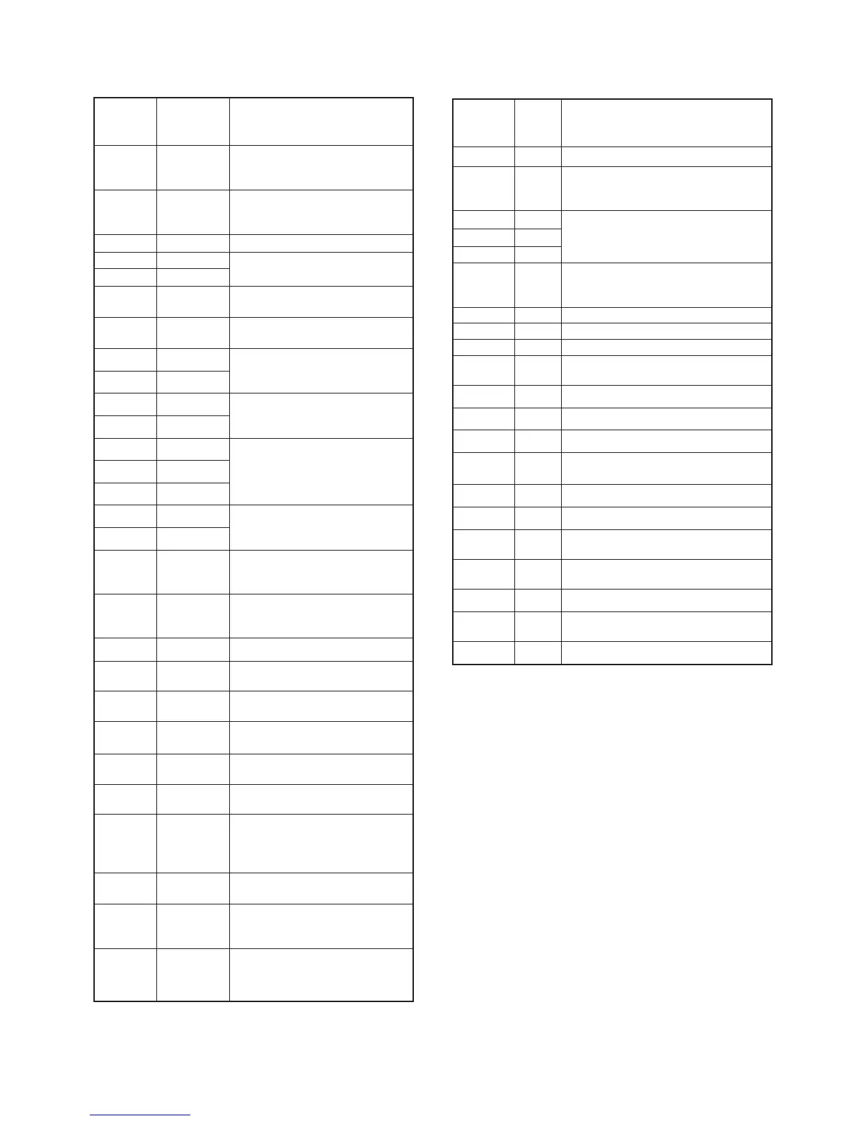
6
Pin
number
Port
name
Description
1 TEMP
Input port for the transceiver’s
internal temperature detecting
signal.
2BATV
Input port for the detect signal
for connecting battery pack’s
voltage.
7 RES
Input port for power reset signal.
13 SENC0
Output single tone encoder
signal.
14 SENC1
16 DUSE
Outputs DTSC LPF control
signal.
18 AFON
Outputs AF power amplifier
control signal.
19 SENC2
Output single tone encoder
signal.
20 SENC3
21 CBI0
Input ports for rotary selector.
22 CBI1
23 CENC0
Output CTCSS/DTCS signals.
24 CENC1
25 CENC2
26 CBI2
Input ports for rotary selector.
27 CBI3
28 SCK
Outputs serial clock signal to
the PLL IC (IC4, pin 9), D/A
convertor (IC6, pin 7), etc.
29 SO
Outputs serial data to the PLL IC
(IC6, pin 8) and D/A convertor
(IC6, pin 8).
30 BEEP
Outputs beep audio signals.
31 ESDA
I/O port for data signals from/to
the EEPROM (IC15, pin 5).
32 ESCL
Outputs clock signal to the
EEPROM (IC15, pin 6).
33 UNLK
Input port for unlock signal from
PLL IC.
34 PLST
Outputs strobe signals to the
PLL IC (IC4, pin 11).
36 NWC
Output/input port for wide/
narrow control signal.
37 DAST
• Outputs strobe signals to the
D/A convertor (IC8, pin 6).
• Input port for the connecting
battery type detect signal.
38 S5C
Outputs power save control
signal.
39 T5C
Outputs T5 regurator control
signal.
Low: While transmitting
40 R5C
Outputs R5 regurator control
signal.
Low: While receivinging
Pin
number
Port
name
Description
42 RLED Outputs receiving LED control signal.
43 TLED
Outputs transmitting LED control
signal.
44 OPT3
I/O ports for option unit.
45 OPT1
46 OPT2
47 PTT
Input port for the PTT switch detection
signal.
Low : While the PTT switch is pushed.
48 SI
Serial Bus inputport.
49 CLI
Input port for the cloning data signal.
50 CLO
Outputs the cloning data signal.
53 NOIS
Input port for the noise signal from the
FM IF IC (MAIN unit; IC1, pin 13).
54 CIRQ Input port for option unit detection.
55 CCS Outputs chip select signal.
56 TMUT Outputs transmit mute signal.
57 RMUT
Input port for AF mute signal from the
RX circuit.
58 MMUT Outputs MIC mute signal.
59 REMO Inputs key signal from remote mic.
60 CDEC
Input port for CTCSS/DTCS signal
from the amplifier (IC5, pin 8).
61 SDEC
Input port for single tone decode
signal from the LPF (IC5, pin 8).
62 KEY Inputs key input signal.
63 RSSI
Input port for the S-meter signal from
the FM IF IC (IC1, pin 12).
64 LVIN
Input port for the PLL lock voltage
.
4-6-2 CPU (IC13)
4 - 6
 Loading...