5 - 4
ADJUSTMENT ADJUSTMENT CONDITION
MEASUREMENT
VALUE
UNIT LOCATION
PLL LOCK
VOLTAGE
[LV (RX LVA)]
[LV (TX LVA)]
1 • Operating Channel : CH7
• Receiving
PC
screen
Check the "LVIN" item on the
CS-F33G ADJ's screen.
3.5 V
3.5 V
2 • Operating Channel : CH7
• Transmitting
CONVENIENT:
The PLL lock voltage can be adjustment automatically.
Set the cursor to "RX LVA"/"TX LVA" and then push [ENTER] key.
3 • Operating Channel : CH5
• Receiving
PC
screen
Check the "LVIN" item on the
CS-F33G ADJ's screen.
1.0–1.6 V
(Verify)
4 • Operating Channel : CH5
• Transmitting
1.0–1.6 V
(Verify)
REFERENCE
FREQUENCY
[REF]
1 • Operating Channel : CH7
• Connect the RF power meter or 50
Ω
dummy
load to the antenna connector.
• Transmitting
Top
panel
Loosely couple the frequency
counter to the antenna con-
nector.
174.0000 MHz
OUTPUT
POWER
[Power (Hi)]
1 • Operating Channel : CH1
• Transmitting
Top
panel
Connect the RF power meter
to the antenna connector.
5.0 W
[Power (L2)] 2 • Operating Channel : CH2
• Transmitting
2.0 W
[Power (L1)] 3 • Operating Channel : CH3
• Transmitting
1.0 W
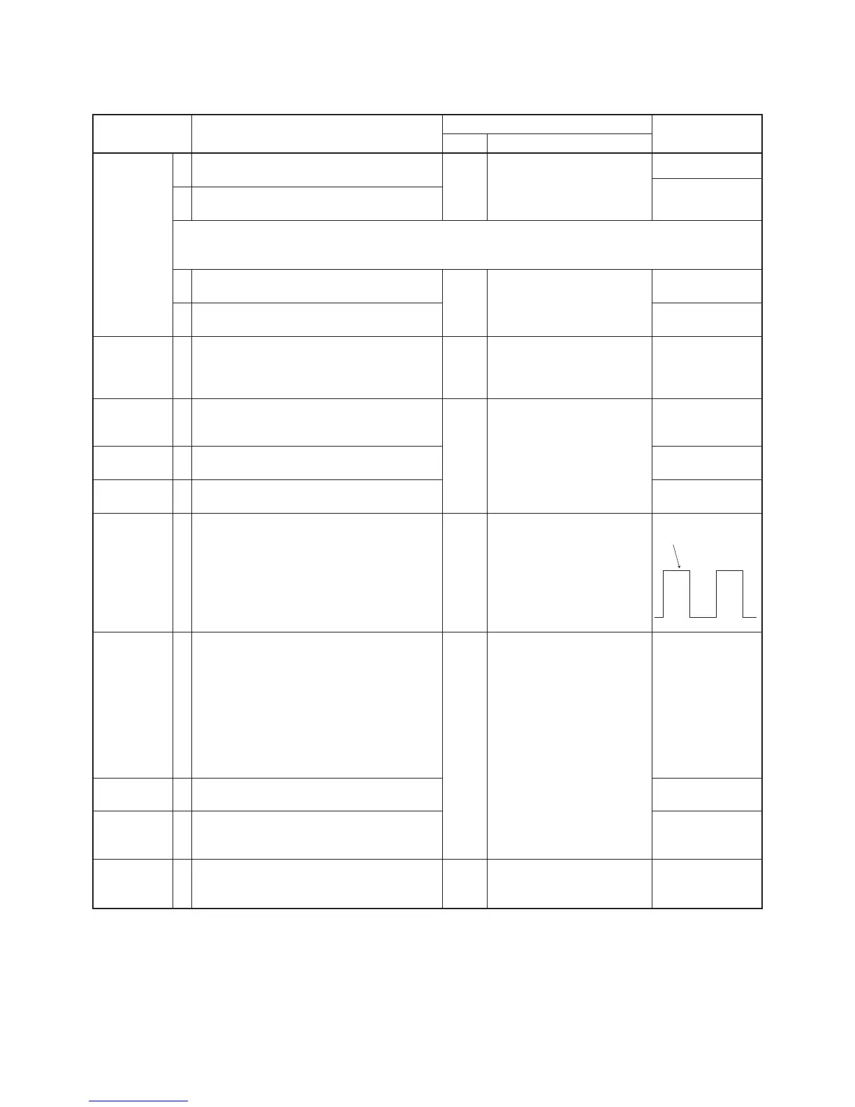
MODULATION
BALANCE
[BAL]
1 • Operating Channel : CH4
• No audio applied to the [MIC] connector.
• Set the FM deviation meter as:
HPF : OFF
LPF : 20 kHz
De- emphasis : OFF
Detector : (P–P)/2
• Push [P0] while transmitting
Top
panel
Connect the FM deviation
meter with the oscilloscope
to the antenna connector
through the attenuator.
Set to square wave
form
FM
DEVIATION
[MOD N]
(Narrow)
1
• Operating Channel : CH4
• Set the FM deviation meter as:
HPF : OFF
LPF : 20 kHz
De- emphasis : OFF
Detector : (P–P)/2
• Connect the audio generator to the [MIC]
connector and set as
: 1.0 kHz/150 mVrms
• Transmitting
Top
panel
Connect the FM deviation
meter to the antenna connec-
tor through the attenuator.
±
2.10 kHz
[MOD Ratio]
(Wide)
2
• Operating Channel : CH1
• Transmitting
±
4.10 kHz
[MOD Ratio]
(Middle)
(F34G only)
3
• Operating Channel : CH8
• Transmitting
±
3.20 kHz
CTCSS/DTCS
DEVIATION
[CTCSS/DTCS]
1
• Operating Channel : CH6
• No audio applied to the [MIC] connector.
• Transmitting
Top
panel
Connect the FM deviation
meter to the antenna connec-
tor through the attenuator.
±
0.70 kHz
5-2 SOFTWARE ADJUSTMENT (TRANSMITTING)
Select an operation using [
↑
] / [
↓
]keys, then set specifi ed value using [
←
] / [
→
] keys on the connected computer keyboard
 Loading...