SECTION 3 DISASSEMBLY INSTRUCTIONS
3 - 1
Chassis unit
E
A
B
C
D
F
Main shield
Main unit
K
K
J
J
L
J
I
G
H
Chassis unit
M
N
N
•
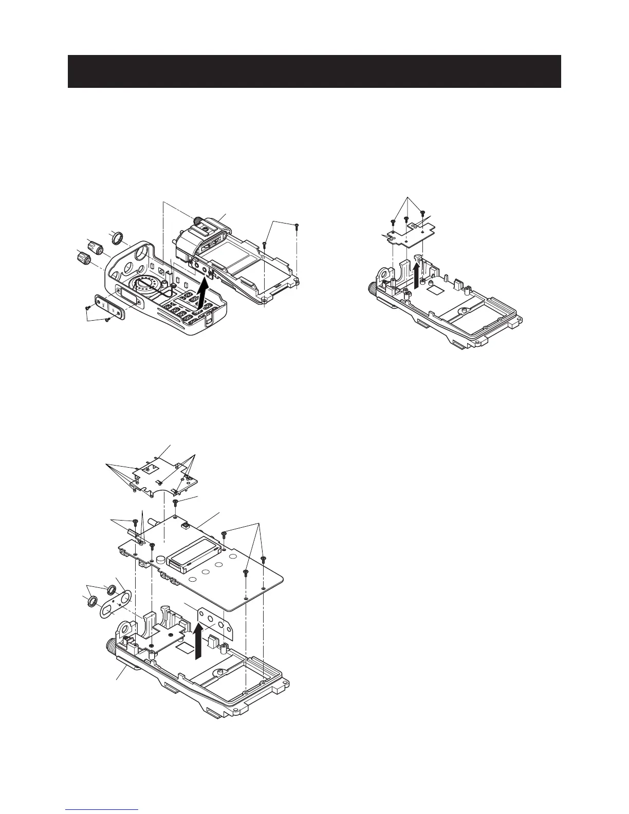
REMOVING THE CHASSIS UNIT
1 Unscrew 1 nut A, and remove 2 knobs B, C.
2 Unscrew 2 screws D.
3 Unscrew 2 screws E.
4 Take off the chassis unit in the direction of the arrow.
5 Unplug the connector F from the chassis unit.
•
REMOVING THE PA UNIT
1 Unscrew 3 screws M.
2 Unsolder 4 points N, and take off the PA unit in the
direction of the arrow.
•
REMOVING THE MAIN UNIT
1 Unscrew 2 nuts G, and remove the top plate H.
2 Remove the side plate I.
3 Unscrew 6 screws J.
4 Unsolder 8 points K, and remove the main shield.
5 Unsolder 2 points L, and take off the main unit in the
direction of the arrow.
 Loading...