Do you have a question about the Icom IC-F3S and is the answer not in the manual?
Covers frequency range, emission type, channels, power supply, temperature, dimensions, and weight.
Details output power, modulation, frequency deviation, emissions, distortion, sensitivity, and selectivity.
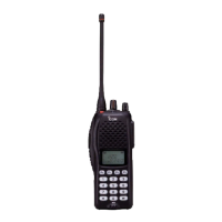
Top and bottom views of the IC-F3/S main unit with component labels.
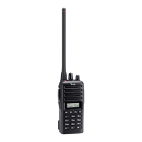
Top and bottom views of the IC-F4/S main unit with component labels.
Provides step-by-step instructions for removing the chassis panel and the main unit.
Instructions for installing optional units like UT-80, UT-96, and UT-105.
Explains receiver circuit functions including antenna switching, RF circuits, mixers, IF stages, and demodulation.
Details microphone amplifier, modulation, drive/power amplifier circuits.
Explains PLL circuit role and details power supply voltage lines.
Lists CPU and expander IC port assignments and functions.
Lists test equipment, software, and initial steps for performing adjustments.
Covers PLL, Trimmer, Transmitter, and Receiver adjustments for IC-F3/S.
Covers PLL, Trimmer, Transmitter, and Receiver adjustments for IC-F4/S.
Lists components for the IC-F3/F3S main unit.
Lists components for the IC-F4/F4S main unit.
Lists chassis and main unit parts for IC-F3/S and IC-F4/S.
Lists optional accessories and their associated diagrams.
Provides schematic symbols and internal views for transistors, FETs, and diodes.
Shows the top view component layout of the IC-F3/S main unit.
Displays the top view component layout for the IC-F4/S main unit.
Presents the block diagram for the IC-F3/S transceiver.
Shows the block diagram for the IC-F4/S transceiver.
Illustrates the voltage distribution within the IC-F3/S.
Depicts the voltage distribution for the IC-F4/S.
| Brand | Icom |
|---|---|
| Model | IC-F3S |
| Category | Transceiver |
| Language | English |