5 - 4
5-2 SOFTWARE ADJUSTMENTS (TRANSMITTING)
Select an operation using [↑] / [↓] keys, then set specified value using [←] / [→] keys on the connected computer keyboard.
1
2
3
4
1
1
2
3
1
2
3
1
2
3
• Operating CH : CH3
• Receiving
• Operating CH : CH3
• Transmitting
• Operating CH : CH11
• Receiving
• Operating CH : CH11
• Transmitting
• Operating CH : CH3
• Connect an RF power meter or 50 Ω
dummy load to the antenna connector.
• Transmitting
• Operating CH : CH1
• Transmitting
• Operating CH : CH2
• Transmitting
• Operating CH : CH3
• Transmitting
• Operating CH : CH7
• Set the FM deviation meter as:
HPF : OFF
LPF : 20 kHz
De-emphasis : OFF
Detector : (P–P)/2
• Connect the audio generator to the multi
connector through the JIG cable (*OPC-
966) and set as :
1.0 kHz/150 mVrms
• Transmitting
• Operating CH : CH8
• Transmitting
• Operating CH : CH9
• Transmitting
• Operating CH : CH4
• No audio applied to the [MIC] input.
• Set an FM deviation meter as:
HPF : OFF
LPF : 20 kHz
De-emphasis : OFF
Detector : (P–P)/2
• IF bandwidth : Narrow
• Transmitting
• Operating CH : CH5
• Transmitting
• Operating CH : CH6
• Transmitting
• Operating CH : CH10
• No audio applied to the [MIC] input.
• Transmitting
PLL LOCK
VOLTAGE
[LV (RX LVA)]
[LV (TX LVA)]
REFERENCE
FREQUENCY
[REF]
OUTPUT
POWER
[Power (Hi)]
[Power (L2)]
[Power (L1)]
FM
DEVIATION
[MOD N]
(Narrow)
[MOD Ratio]
(Middle)
[MOD Ratio]
(Wide)
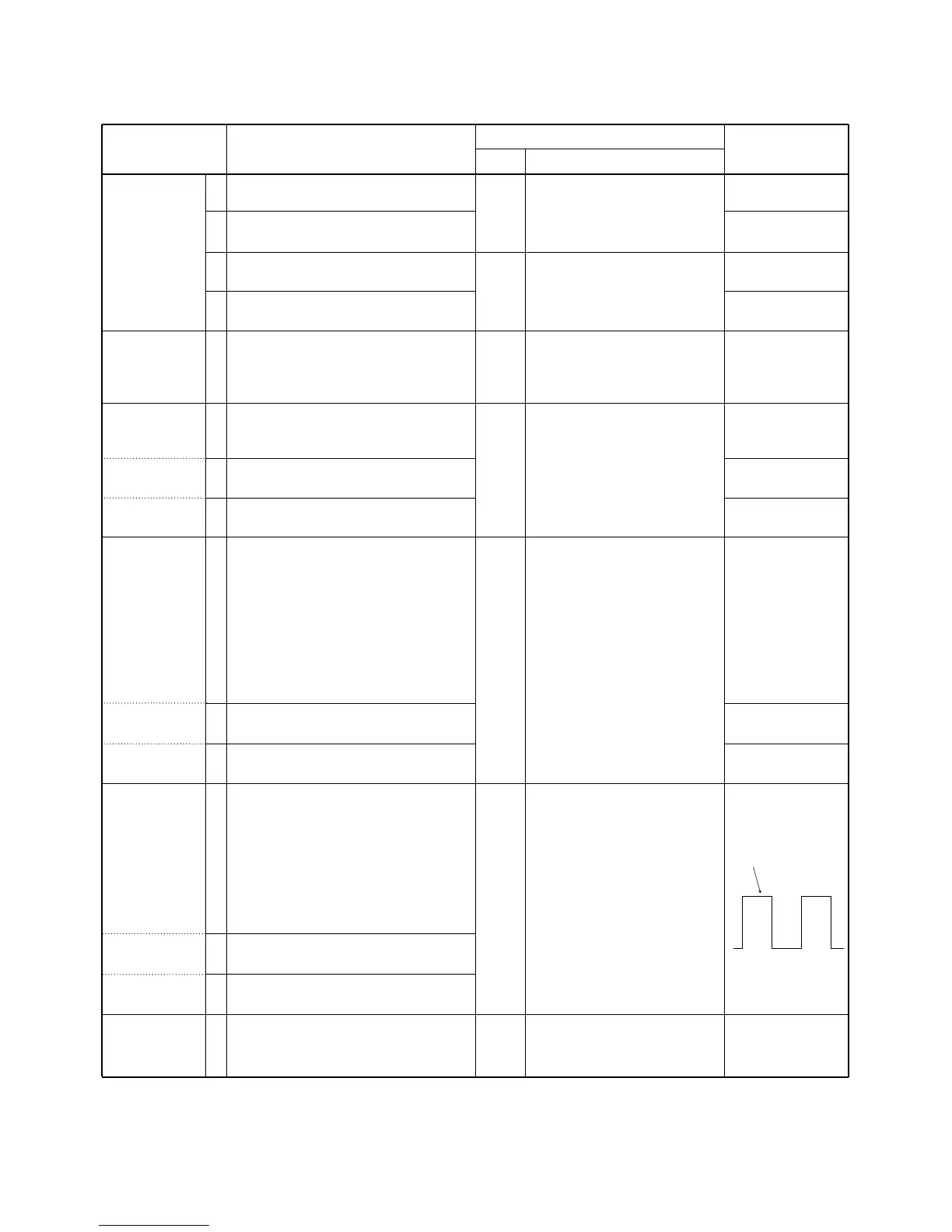
MODULATION
BALANCE
[BAL N]
(Narrow)
[BAL Ratio]
(Middle)
[BAL Ratio]
(Wide)
CTCSS/DTCS
DEVIATION
[CTCS/DTCS]
Soft
ware
Soft
ware
Top
panel
Top
panel
Top
panel
Top
panel
Check the “LV” item on the CS-
F50 ADJ’s display.
Check the “LV” item on the CS-
F50 ADJ’s display.
Connect a digital multimeter to
the “LV” line.
Loosely couple a frequency
counter to the antenna connec-
tor.
Connect an RF power meter to
the antenna connector.
Connect an FM deviation meter
to the antenna connector
through the attenuator.
Connect an FM deviation meter
with an oscilloscope to the
antenna connector through an
attenuator.
Connect an FM deviation meter
to the antenna connector
through the attenuator.
3.5 V
3.5 V
0.9–1.5 V
(Verify)
0.9–1.5 V
(Verify)
174.0000 MHz
5.0 W
2.0 W
1.0 W
±2.10 kHz
±3.20 kHz
±4.10 kHz
±0.68 kHz
ADJUSTMENT ADJUSTMENT CONDITION
MEASUREMENT
VALUE
UNIT LOCATION

 Loading...