4 - 2
P
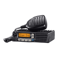
Optional UT-96R or UT-119H installation
Install the optional UT-96R or UT-119H unit as follows:
q
Turn the power OFF, then disconnect the DC power cable.
w
Unscrew the 4 cover screws, then remove the bottom cover.
e
Install the UT-96R to J1 and the UT-119H to J2 as shown
in the diagram below.
r
Remove the protective paper from the supplied sponge,
then attach it on the installed unit.
t
Replace the bottom cover and screws, then re-connect
the DC power cable.
Front panel
Sponge
UT-96R
J1
J2
A
B
Front panel
P
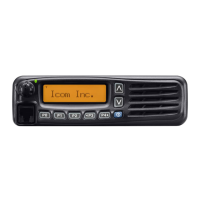
Optional UT-109R or UT-110R installation
q
Turn the power OFF, then disconne ct the DC power cable.
w
Unscrew the 4 cover screws, then remove the bottom cover.
e
Cut the pattern on the PCB at the A (MIC) and B (AF OUT)
as shown below.
r
Install the scrambler unit to J1 as described in the instal-
lation of optional UT-96R installation as above.
t
Remove the protective paper from the supplied sponge,
then attach it on the installed unit.
y
Replace the bottom cover and screws.
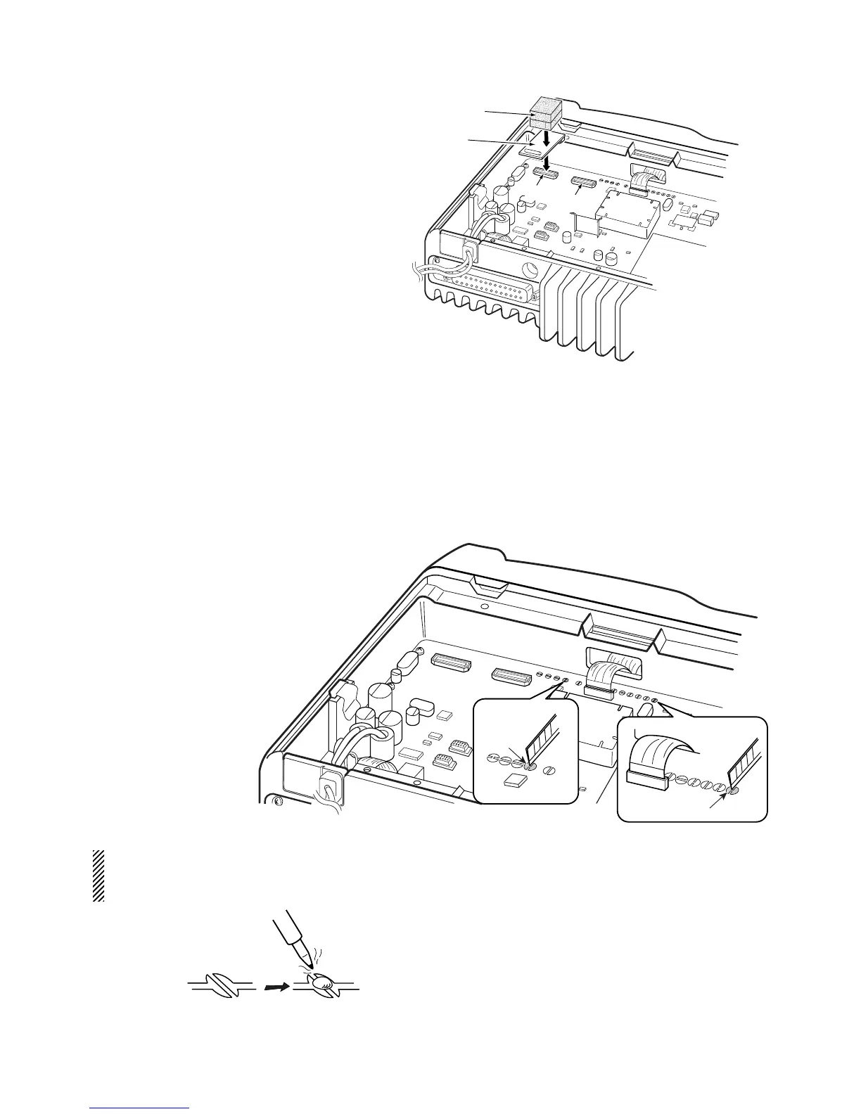
Re-solder
NOTE: When uninstalling the unit
Be sure to re-solder the disconnected points as below
when you remove the unit. Otherwise no TX modulation or
AF output is available.
*This illustration describes the UT-96R installation.
 Loading...