17
D Receiving a Message
Not available on Non-display types.
q When a Message is received;
• Beeps sound.
• The calling station ID (or alias) and the message are displayed
alternately.
w Turn power OFF, push [PTT], change the channel, etc. to
stop the display indication.
D Receiving a Status Message
Not available on Non-display types.
➥ When a Status Message is received;
• Beeps sound.
• The calling station ID (or alias) and the status message are dis-
played once.
MDC 1200 SYSTEM OPERATION
3
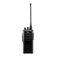
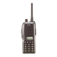
For Handhelds:
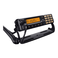
For Mobiles:
MSGL 1 MG
MSG 1
MDC SELC CALA
ID 1234
T
ID 1234
MDC SELC CALA
For Handhelds:
For Mobiles:
STAT US1
STATUS1
MDC SELC CALA
ID 1234
T
ID 1234
MDC SELC CALA
 Loading...