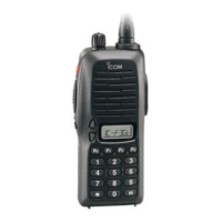
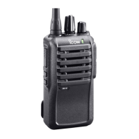
Do you have a question about the Icom IC-F4S and is the answer not in the manual?
Top and bottom views with component labels for the IC-F3/S main unit.
Top and bottom views with component labels for the IC-F4/S main unit.
Step-by-step guide for removing chassis panel and main unit.
Instructions for installing optional units like UT-80, UT-96, UT-105.
Detailed explanation of receiver circuit blocks: RF, IF, demodulator, AF, and squelch.
Explanation of transmitter circuit blocks: microphone, modulation, power, and APC.
Description of the Phase-Locked Loop circuit for frequency stability.
Details on various voltage lines and their regulation for device operation.
Mapping of CPU and expander IC ports to functions and signals.
List of required test equipment and software for calibration procedures.
Procedure for adjusting PLL lock voltage for IC-F3/S and IC-F4/S.
Calibration of Reference Frequency, Output Power, and FM Deviation for IC-F3/S.
Adjusting DTCS wave form and FM deviation for IC-F3/S and IC-F4/S.
Adjusting Squelch Level for IC-F3/S and IC-F4/S.
List of components for the main unit of IC-F3/F3S radios.
List of components for the main unit of IC-F4/F4S radios.
List of external cabinet parts for IC-F3/S and IC-F4/S.
List of optional accessories and their part numbers.
Diagrams and names for transistors and FETs used in the device.
Diagrams and names for diodes used in the device.
Top view layout of the IC-F3/S main unit PC board with component placement.
Layout of the common VR board showing connections to the main unit.
Top view layout of the IC-F4/S main unit PC board with component placement.
Block diagram illustrating the circuit architecture for the IC-F3/S.
Block diagram illustrating the circuit architecture for the IC-F4/S.
Voltage distribution diagram for the IC-F3/S main unit and VR board.
Voltage distribution diagram for the IC-F4/S main unit and VR board.
| Type | Handheld transceiver |
|---|---|
| Frequency Range | 136-174 MHz |
| Mode | FM |
| Voltage | 7.2V |
| Power Output | 5W |
| Battery Life | Approx. 8 hours |
| Weight | 350 g (including battery) |
| Power supply requirement | 7.2V DC |