Do you have a question about the Icom IC-F420S and is the answer not in the manual?
Emphasizes reading all instructions before use and keeping the manual for future reference.
Explains the meaning of WARNING, CAUTION, and NOTE indicators for user safety.
Warns against improper electrical connections, environmental exposure, and unauthorized access.
Details safe operating temperatures, placement, and ventilation requirements for the transceiver.
Warns against using chemical solvents for cleaning to prevent surface damage.
Notifies users that unauthorized modifications void FCC operating authority.
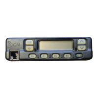
Identifies and locates all controls on the transceiver's front panel.
Explains the meaning of icons and readouts on the transceiver's display.
Details the operation of volume, channel keys, power switch, and microphone connector.
Explains the assignment and use of various programmable function keys.
Guides through powering on the transceiver, including password entry.
Details different methods for selecting operating channels based on system setup.
Explains fundamental steps for receiving calls and transmitting signals.
Covers Tx code channel/number selection and DTMF transmission capabilities.
Illustrates the rear panel layout and connection points for accessories.
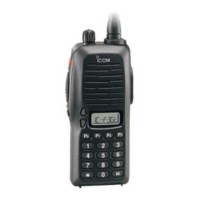
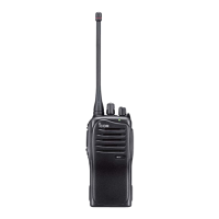
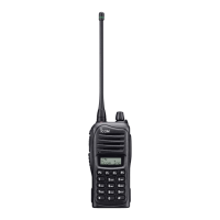
Lists and describes the components included with the transceiver.
Provides instructions for securely mounting the transceiver using the supplied bracket.
Details the installation process for optional UT-96/UT-105 units.
Covers antenna considerations, fuse replacement, and basic cleaning procedures.
Explains SmarTrunk II™ functions and conventional channel compatibility.
Guides on placing, receiving, and answering calls within the SmarTrunk II™ system.
Details terminating calls, last number redial, and memory speed-dialing.
Covers programming speed dial, system busy indications, and dispatch operations.
Outlines the steps for initiating an emergency call.
Explains the process of searching for and alerting to available open channels.
Details the specifications for optional external speakers SP-5 and SP-10.
Describes the HM-100T/TA DTMF and HM-100 normal microphones.
Lists optional units including 5-tone unit, SmarTrunk II™ logic board, and ACC cable.
| Frequency Range | 400-470 MHz |
|---|---|
| Power Output | 5W |
| Channel Capacity | 16 channels |
| Modulation Type | 16K0F3E |
| Battery Life | 10 hours |
| Channel Spacing | 25 kHz |