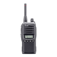
Do you have a question about the Icom IC-F4001 and is the answer not in the manual?
Details general parameters like frequency range, channels, and dimensions.
Outlines output power, modulation, and frequency deviation limits.
Details receiver sensitivity, squelch, and audio output parameters.
Illustrates component placement on the main board's top side.
Illustrates component placement on the main board's bottom side.
Step-by-step guide for safely removing the transceiver's chassis.
Procedure for detaching the main electronic unit from the chassis.
Explains the signal path and components within the receiver section.
Details the signal path and components for transmitting.
Describes the circuits responsible for frequency generation and control.
Provides a schematic overview of the transceiver's voltage distribution.
Lists pin assignments for CPU and D/A converter for interface details.
Lists the necessary equipment and setup for calibration procedures.
Instructions for creating and uploading specific cloning files for calibration.
Guide to using the software utility for transceiver adjustments.
Procedure for calibrating the transceiver's frequency settings.
Procedure for adjusting transmit output power and modulation.
Procedure for calibrating receiver sensitivity and squelch.
Lists and details the mechanical components for the transceiver chassis.
Details the included accessories supplied with the transceiver.
Diagram showing component placement on the top of the main circuit board.
Diagram showing component placement on the bottom of the main circuit board.
Illustrates voltage distribution across the main unit's first section.
Illustrates voltage distribution across the main unit's second section.
| Channel Capacity | 16 channels |
|---|---|
| Power Output | 5W |
| Water Resistance | IP54 |
| Mode | FM |
| Voltage | 7.2V |
| Channel Spacing | 12.5 kHz |
| Frequency Range | 400-470 MHz |
| Operating Voltage | 7.2V |
| Operating Temperature | -30°C to +60°C |