Tx = f
3
Rx = f
4
IC-FR3000 IC-FR3000
Basic Repeater Linking System
Basic Repeater Linking SystemBasic Repeater Linking System
Basic Repeater Linking System
54
Connection example
Connection exampleConnection example
Connection example
This is an advanced plan to upgrade the repeater site to
a link system. An ICOM repeater also works as a base
station (simplex), therefore this system is more versatile.
Applicable for repeater link, cross-band repeater, etc..
System requirement (One site)
System requirement (One site)System requirement (One site)
System requirement (One site)
UHF H/H UHF H/H
Descriptions Model Number Quantity
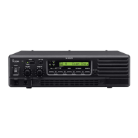
UHF Repeater IC-FR4000
UHF Antenna
Duplexer
VHF Repeater IC-FR3000
VHF Antenna
Duplexer
Interface Cable 25p to 25p
Connect two repeaters by interface cable (25p to 25p).
These interface cables are not sold as Icom accessories,
therefore please assemble the interface cable by
yourself. The connection diagram is as follows;
 Loading...