Do you have a question about the Icom IC-FR4000 Series and is the answer not in the manual?
Introduction to the handbook and its purpose.
Legal disclaimers regarding accuracy, changes, IPR, and copyrights.
Lists registered trademarks and notes on application examples.
Details about Icom Inc., its history, quality, production, brand, and network.
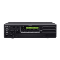
Lists the VHF and UHF FM Repeaters IC-FR3000/FR4000.
Details features like 50W output, backup, memory channels, tones, and signaling.
Describes internal space for duplexer, telephone interconnect, DTMF control, and mounting options.
Discusses U.S. Military specifications and other features.
Compares functions and specifications for VHF models.
Compares functions and specifications for UHF models.
Describes mounting brackets (MB-77, MB-78) and microphones (SM-25, HM-152).
Lists cloning cables (OPC-592, OPC-478) and software (CS-FR3000).
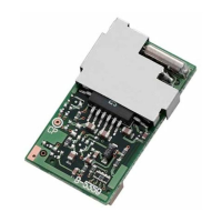
Describes UT-109 and UT-110 voice scrambler units.
Explains the front panel controls, indicators, and display.
Details switches like ANI CLR, PROG, indicators, and function display.
Describes connectors like TX/RX ANT, EXT SP, ACC, GND, and DC power terminals.
Lists functions assignable to the [PROG] key (Null, Prio A, Disp Select, etc.).
Details how to program scrambler codes for UT-109/UT-110.
Explains assigning functions like Opening Text and RF Power to the [PROG] key.
Details pin assignments for the 25-pin accessory connector.
Explains pin usage for selecting memory channels.
Details pin assignments for the remote connector.
Instructions for handling unpacked equipment and choosing an installation site.
Advice on antenna connection, duplexer use, and grounding procedures.
Step-by-step guide for N-type connector installation.
Diagrams for microphone, DC power, and antenna connections.
Details LINE connector and EXTERNAL SPEAKER connections.
Explains AC/DC power operation and battery backup.
Instructions for installing the MB-78 rack mount bracket (bottom side).
Continues instructions for MB-78 rack mount bracket (top side).
Instructions for installing the MB-77 wall mount bracket.
Steps to open the repeater's casing for unit installation.
Instructions for installing UT-109/UT-110 voice scrambler units.
Step-by-step guide for installing duplexer and isolator units.
Illustrates connection setups and defines duplexer/isolator.
Lists duplexer models from PROCOM and Radio Frequency Systems.
Lists isolator models from Sinclair and PROCOM.
Guide to installing the CS-FR3000 software on a PC.
Explains connections and overview of the CS-FR3000 software interface.
Recommends reading existing data and selecting model types (LMR/PMR).
Details on editing memory channels within the software.
Details setting items like Key & Display, Common, Expert and DTMF codes.
Details cloning items for 2-Tone and 5-Tone configurations.
Steps to power on the repeater, including password entry, receiving and transmitting.
Describes the backup repeater system setup and function.
Lists required components and programming examples for backup.
Explains multi-tone relaying and programming examples.
Details DTMF settings required for remote control operation.
Explains command formats: basic, with sub code, and with password.
Lists functions, default codes, and mode applicability for remote commands.
Explains the purpose and availability of each remote control command.
General notes on entering commands and examples like Repeat Start.
Example operation for setting RF power to low.
Example operation for setting RF power to high.
Examples for turning RX Unit ON/OFF and TX/RX Units ON/OFF via phone.
Examples for enabling master and slave repeater functions.
Example operation for selecting memory channels.
Example operation for performing a CPU reset.
Overview of the system setup for connecting repeaters to phone lines.
Explains DTMF settings, operation from transceiver (autodial/dial).
Diagram showing connection for phone patch and remote control.
Explains operating phone patch from the phone line (TX Start/Stop).
Explains the basics, features, and applications of 2-Tone signalling.
Explains the basics, formats, and activation of 5-Tone signalling.
Details on the structure and parameters of 5-Tone formats.
Lists advantages and features like selective calling, group calling, and enhancements.
Explains DTMF, its features, and system control capabilities.
Details DTMF codes for System Control, RX System Code, and TX System Code.
Introduces optional scrambler units and their scrambling methods.
Compares UT-109 (non-rolling) and UT-110 (rolling) scramblers.
Details on setting scrambler via Memory CH and Common settings.
Introduces basic repeater linking systems and their setup.
Explains basic linking system diagrams and connection examples.
Diagrams of basic linking systems with IC-FR3000/FR4000.
Lists system requirements and connection examples for linking repeaters.
Diagram of a three-site linking system.
Shows connection example for linking repeaters using different interface cables.
Instructions for opening the case and software configuration for ACC connector.
Manual setting of the REMOTE key function for operation.
Diagrams of single site MPT1327 trunking systems.
Lists requirements for single site MPT1327 trunking systems.
Diagrams and requirements for telephone connection and tracking features.
Diagrams of local and regional sites in a trunking system.
Lists requirements for a regional trunking system.
Introduces single site LTR® trunking systems.
Diagrams of single site LTR® trunking systems with telephone connection.
Lists requirements for single site LTR® trunking systems.
Diagrams of digital networked trunking systems for Site A and Site B.
Lists system requirements for Site A and Site B.
Diagrams of analog networked trunking systems for Site A and Site B.
Lists system requirements for Site A and Site B.
Diagrams and components for DC-only and DC/AC combined solar power systems.
Guidance on calculating daily amp hour usage for solar systems.
Steps to calculate the number of solar panels and battery capacity needed.
Guidance on selecting power cables, controllers, and inverters for solar systems.
Diagrams and components for DC-only and DC/AC combined wind-solar hybrid power systems.
Guidance on designing hybrid systems, turbine power, density, radius, and velocity.
Lists sample wind turbine models and specifications.
Lists sample solar panel models and specifications.
Lists sample controllers, inverters, and other components.
Guide to diagnosing and solving common problems like no power, no sound, low sensitivity.
Instructions for replacing blown fuses in the repeater.
Detailed instructions for replacing fuses in the LOGIC and REG units.
Information on available catalogues and web resources from Icom.
Lists brochures and posters available through local distributors.
Information on available instruction manuals and website resources.
Lists service manuals available through local distributors.
| Dimensions | 483 × 88 × 331.2 mm |
|---|---|
| Weight | 7.5 kg |
| Current Drain | 1.5 A |
| Operating Temperature Range | -30°C to +60°C |
| Channel Spacing | 12.5 / 25 kHz |
| Frequency Range | 136-174 MHz |