Do you have a question about the Icom IC-F3003 and is the answer not in the manual?
Diagram showing component layout on the top side of the main unit board.
Diagram showing component layout on the bottom side of the main unit board.
Circuit diagram detailing voltage distribution on the first half of the main unit.
Circuit diagram detailing voltage distribution on the second half of the main unit.
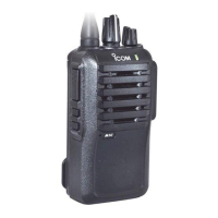
Lists supported transceiver models including IC-F3001, IC-F3002, IC-F3003, IC-F3006, IC-F3008.
Details general operating parameters like frequency range, channels, and dimensions.
Outlines transmitter performance characteristics such as output power and frequency stability.
Describes receiver performance metrics including sensitivity and squelch characteristics.
Labeled diagram of the main unit's top PCB, identifying key components and ICs.
Labeled diagram of the main unit's bottom PCB, identifying key components and ICs.
Step-by-step guide for safely removing the transceiver's chassis.
Procedures for detaching the main electronic unit from the chassis.
Explains the operation of the RF, 1st IF, and 2nd IF circuits in the receiver path.
Details the TX AF circuits, modulation circuit, and TX amplifiers.
Describes the function of the RX and TX VCOs and the PLL IC.
Overview of power supply distribution across different circuit blocks.
Maps CPU and D/A converter pins to their functions and descriptions.
Lists required equipment and setup for performing adjustments.
Diagram illustrating the proper connection of test equipment for adjustments.
Details the cloning file setup for various adjustment channels.
Step-by-step procedure for adjusting transceiver frequencies.
Guides for adjusting transmitter parameters like output power and deviation.
Procedures for setting receiver sensitivity and squelch levels.
Lists all individual parts that constitute the transceiver's chassis.
Details optional accessories and their compatibility with different regions.
| Frequency Range | 136-174 MHz |
|---|---|
| Number of Channels | 16 |
| Channel Spacing | 12.5/25 kHz |
| Power Output | 5W |
| Water Resistance | Yes |
| IP Rating | IP54 |
| Modulation | FM |