EasyManua.ls Logo

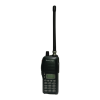
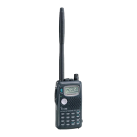
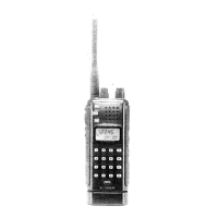
Icom IC-T7H Service Manual

Icom IC-T7H
37 pages
To Next Page IconTo Next Page
Page #1 background imageLoading...
Page #1 background image
SERVICE
MANUAL
DUAL BAND FM TRANSCEIVIER

Other manuals for Icom IC-T7H

Questions and Answers:

Icom IC-T7H Specifications

General IconGeneral
BrandIcom
ModelIC-T7H
CategoryTransceiver
LanguageEnglish

Summary

Introduction

Ordering Parts

Details required information for ordering replacement parts for the transceiver.

Repair Notes

Essential precautions and guidelines to follow during transceiver repair procedures.

Specifications

Inside Views

Logic Unit and 2F Unit

Internal view of the Logic Unit and 2F Unit, highlighting key components.

1F Unit

Internal view of the 1F Unit, showing component layout and identification.

Disassembly Instructions

Disassembling Panels

Instructions for removing the front and rear panels of the transceiver.

Removing 2F Unit

Procedure for safely removing the 2F Unit from the transceiver assembly.

Removing Logic Unit

Steps for detaching and removing the Logic Unit from the main chassis.

Removing 1F Unit

Procedure for unscrewing and removing the 1F Unit assembly.

Circuit Description

Receiver Circuits

Detailed explanation of the transceiver's receiver circuit functions and components.

VHF RF Circuit (2F Unit)

Explanation of the VHF RF circuit operation and signal amplification.

UHF RF Circuit (2F Unit)

Explanation of the UHF RF circuit operation and signal amplification.

1st Mixer and 1st IF Circuits (2F Unit)

Description of the first mixer and IF stage for signal conversion.

2nd IF and Demodulator Circuits (2F Unit)

Description of the second IF stage and demodulation process.

AF Amplifier Circuit (Logic Unit)

Circuit for amplifying and muting AF signals on the logic unit.

AF Power Amplifier Circuit (2F Unit)

Circuit for amplifying AF signals to drive the external speaker.

Noise Squelch Unit (2F Unit)

Circuit that suppresses AF signals based on detected noise levels.

Transmitter Circuits

Explanation of the transceiver's transmitter circuit operations and signal paths.

Microphone Amplifier Circuit (Logic and 2F Unit)

Circuit for amplifying and pre-emphasizing microphone audio input.

Modulation Circuit (Dual VCO Board)

Circuit that modulates VCO signals using audio for frequency shifting.

Power Amplifier Circuit (1F Unit)

Circuit for amplifying RF signals to the final output power level.

APC Circuit (1F and 2F Units)

Circuit for stabilizing and controlling transmit output power levels.

Antenna Switching Circuit (1F Unit)

Circuit to switch antenna between VHF and UHF receive/transmit paths.

VHF Antenna Switching Circuit

Circuit to switch antenna between VHF receive and transmit paths.

UHF Antenna Switching Circuit

Circuit to switch antenna between UHF receive and transmit paths.

PLL Circuits

Explanation of the Phase-Locked Loop (PLL) circuits for frequency control.

VHF PLL Circuit (1F Unit)

PLL circuit for stabilizing VHF transmit and receive frequencies.

UHF PLL Circuit (1F Unit)

PLL circuit for stabilizing UHF transmit and receive frequencies.

Power Supply Circuits

Details on the different voltage lines and their sources within the transceiver.

Other Circuits

Description of auxiliary circuits such as tone squelch and port allocations.

Tone Squelch Circuit (Logic Unit)

Circuit that opens squelch only for signals with a matched subaudible tone.

Port Allocations

List of port functions and their assigned descriptions for input/output.

CPU (Logic Unit; IC1) Port Allocations

List of CPU port functions and their assigned descriptions for input/output.

Adjustment Procedures

PLL and Transmitter Adjustment

Procedures for adjusting the PLL and transmitter parameters for optimal performance.

Receiver Adjustment

Procedures for adjusting receiver sensitivity and squelch levels.

Parts List

Mechanical Parts and Disassembly

Chassis Parts

List of mechanical parts for the main chassis of the transceiver.

Logic Unit Parts

List of mechanical parts specific to the Logic Unit assembly.

Unpacking Information

Details on optional products and accessories included with the transceiver.

1F Unit Parts

List of mechanical parts for the 1F Unit.

PA Board Parts

List of mechanical parts for the PA Board.

Dual VCO Board Parts

List of mechanical parts for the Dual VCO Board.

Semi-Conductor Information

Transistors and FET's

Information and symbols for various transistors and FETs used in the device.

Diodes

Information and symbols for various diodes used in the device.

Board Layouts

Logic Unit Board Layout

Top view layout of the Logic Unit PCB with component placement.

Logic Unit Bottom View

Bottom view layout of the Logic Unit PCB, showing component placement.

2F Unit Board Layout

Top view layout of the 2F Unit PCB, indicating component positions.

Dual VCO Board Top View

Top view layout of the Dual VCO Board, showing component placement.

2F Unit Bottom View

Bottom view layout of the 2F Unit PCB, showing component placement.

Dual VCO Board Bottom View

Bottom view layout of the Dual VCO Board, showing component placement.

1F Unit Board Layout

Top view layout of the 1F Unit PCB, indicating component positions.

PA Unit Top View

Top view layout of the PA Unit, showing component placement.

1F Unit Bottom View

Bottom view layout of the 1F Unit PCB, showing component placement.

PA Unit Bottom View

Bottom view layout of the PA Unit, showing component placement.

Block Diagram

Voltage Diagram

Logic Unit Voltage Diagram

Voltage distribution diagram for the Logic Unit circuitry.

1F Unit Voltage Diagram

Voltage distribution diagram for the 1F Unit circuitry.

2F Unit Voltage Diagram

Voltage distribution diagram for the 2F Unit circuitry.

Related product manuals