EasyManua.ls Logo

Icom IC-T2H Service Manual

Icom IC-T2H
28 pages
To Next Page IconTo Next Page
Page #1 background imageLoading...
Page #1 background image
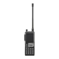
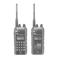
144 MHz FM TRANSCEIVER
iC-t2h
iC-t2e-t

Other manuals for Icom IC-T2H

Questions and Answers:

Icom IC-T2H Specifications

General IconGeneral
Frequency Range144-146 MHz
ModulationFM
Power Output5W
Weight320g
RF Power Output5W
Voltage9.6 VDC

Summary

Introduction and Safety Information

Critical Safety Warnings

Essential safety precautions to prevent hazards like electric shock and fire.

Ordering Replacement Parts

Guidelines for specifying and ordering correct replacement components.

Service Repair Notes

Important considerations and best practices for performing repair procedures.

Specifications Overview

General Device Specifications

Covers frequency range, mode, current drain, and other general operational parameters.

Transmitter Performance

Details output power, modulation system, frequency deviation, and spurious emissions.

Receiver Performance

Outlines receive system, intermediate frequencies, sensitivity, selectivity, and audio output.

Internal Unit Views

Main Unit Component Layout

Top and bottom views identifying key components on the main circuit board.

Disassembly and Servicing

Chassis Panel Removal Procedure

Step-by-step guide for safely removing the external chassis panel.

Main Unit Disassembly

Instructions for detaching the main circuit board assembly from the chassis.

Circuitry Description

Receiver Circuitry Breakdown

Explanation of antenna switching, RF amplification, and mixer stages.

Transmitter Circuitry Breakdown

Details microphone amplification, modulation, and power amplifier stages.

PLL and Power Supply Circuits

Description of the Phase-Locked Loop and voltage regulation circuits.

CPU Port Functionality

Allocation and function of input/output ports on the central processing unit.

Adjustment Procedures

Test Equipment and Connections

Lists necessary test equipment and illustrates required connection configurations.

PLL and Transmitter Tuning

Step-by-step guide for adjusting PLL, output power, and FM deviation.

Receiver Tuning and Squelch

Procedures for calibrating receiver sensitivity and setting squelch levels.

Component Parts List

Main Unit Component List

Detailed list of components used in the main unit with part numbers.

Mechanical Components and Assembly

Cabinet and Chassis Parts List

Inventory of all external cabinet and internal chassis-mounted parts.

Included Accessories

List of items supplied with the transceiver, such as chargers and battery cases.

Semiconductor Component Details

Transistor Specifications and Views

Identification and internal schematic views for all transistors.

Diode Specifications and Views

Identification and internal schematic views for all diodes.

Printed Circuit Board Layouts

Main Unit PCB Layout

Top view diagram showing component placement on the main circuit board.

VR Board PCB Layout

Top view diagram showing component placement on the VR circuit board.

VCO Board PCB Layout

Top view diagram showing component placement on the VCO circuit board.

System Block Diagram

Voltage Distribution Diagram

Related product manuals