EasyManua.ls Logo

Icom IC-U200 - User Manual

Icom IC-U200
16 pages
Print Icon
To Next Page IconTo Next Page
Loading...
INSTRUCTION
MANUAL
POWER
/V¥O
%
iN
VHF
FM
TRANSCEIVER
IC—V200
UHF
FM
TRANSCEIVER
IC—U200
re)
:
ICOM
1C-uU200..
Icom
Inc.
Question and Answer IconNeed help?

Do you have a question about the Icom IC-U200 and is the answer not in the manual?

Summary

INSTALLATION

VEHICLE INSTALLATION

Select a location that supports the transceiver, marks screw holes, drills, and mounts the bracket.

POWER REQUIREMENTS

Transceiver operates on 13.8V DC, 7A negative ground. Voltages >16V DC will damage.

ANTENNA

Antenna is critical for performance; a high-quality 50Ω 5/8 wavelength antenna is recommended.

CONTROL FUNCTIONS

FRONT PANEL

Describes controls like Power/Volume, Monitor Switch, Squelch Control, and indicators like TX, Busy, Call.

REAR PANEL

Details connections for Antenna Connector, External Speaker Jack, Power Connector, and Horn Connector Cables.

OPERATION

RECEIVING

Steps for receiver presettings: Monitor ON, Power/Volume clockwise, Squelch control to quiet noise.

MONITOR FUNCTION

Allows listening to busy channels regardless of tone programming or microphone hanger status.

TRANSMITTING

Push PTT to transmit, speak normally, release PTT to return to receiving. Avoid transmitting when BUSY indicator is ON.

HORN-HONK FUNCTION

Transceiver alerts operator via signalling device when a correct code number is decoded; requires optional units.

SPECIFICATIONS

OPTIONS AND PRODUCTS

Overview

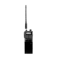
The Icom IC-V200 VHF FM Transceiver and IC-U200 UHF FM Transceiver are advanced mobile communication devices designed for the Land Mobile market. These transceivers leverage sophisticated computer-based technology and Icom's precision VHF/UHF engineering to offer state-of-the-art design concepts, meeting the demanding needs of Land Mobile users.

Function Description:

The IC-V200 and IC-U200 are two-way radio transceivers, meaning they are capable of both transmitting and receiving radio signals. The IC-V200 operates on VHF (Very High Frequency) bands, while the IC-U200 operates on UHF (Ultra High Frequency) bands. They are designed for mobile use, typically installed in vehicles, to facilitate communication within a defined network or group.

Usage Features:

Installation:

The transceivers are designed for vehicle installation. Users should select a location that can support the device's weight and does not interfere with driving. The mounting bracket is used to mark screw holes, ensuring controls and switches are easily accessible and the display is clearly visible. After drilling, the bracket is mounted, and the screws are tightened. A grounding lead should be connected from the transceiver to the vehicle's chassis ground. A microphone hanger is also provided for convenient storage of the microphone.

Power Requirements:

The transceivers operate on a regulated 13.8V DC, 7A negative ground source. A 12V negative ground system is suitable. It is crucial to note that voltages greater than 16V DC will damage the transceiver, so users must verify the source voltage before connecting the power cable. For vehicles with a 24V battery, direct connection is not possible, and installation information should be sought from an Icom Dealer or Service Center.

Antenna Connection:

The performance of the communication system heavily relies on the antenna. A high-quality 50Ω 5/8 wavelength antenna is recommended for mobile applications. The antenna connects to the transceiver via a PL-259 type connector.

External Speaker:

An optional SP-5 external speaker can be connected to the transceiver, accepting a 2 to 8Ω external speaker. This enhances audio clarity for more reliable communications.

Front Panel Controls:

  • POWER/VOLUME Control: This knob serves a dual purpose: turning the transceiver ON and OFF and adjusting the audio output level.
  • MONITOR Switch: This switch toggles the monitor function ON and OFF. When activated, it allows listening to a busy channel even if the microphone is in its hanger or if a tone is not programmed for the channel.
  • SQUELCH Control: This control sets the squelch threshold level, effectively muting weak incoming signals. Rotating it clockwise increases the threshold, quieting noise until a strong enough signal is received. If unwanted weak signals are still heard, rotating it slightly more clockwise can correct this.
  • CHANNEL Select Switch: This rotary switch allows the user to select an operating channel.

Indicators:

  • TRANSMIT (TX) Indicator: Lights up when the transceiver is actively transmitting.
  • BUSY Indicator: Illuminates when the transceiver is receiving signals or when the squelch is open.
  • CALL Indicator: Lights up when a signal is received with the same programmed tone as the one in the transceiver.
  • POWER (PWR) Indicator: Lights up when the POWER/VOLUME control is turned ON.

Microphone Connector:

The microphone connects to the transceiver via this port.

Receiving Operations:

  1. Receiver Presettings:

    • Push the [MONITOR] switch ON (in position).
    • Rotate the [POWER/VOLUME] control clockwise. The [PWR] indicator will light up.
    • Rotate the [SQUELCH] control fully counterclockwise. The [BUSY] indicator will light up. Adjust the [POWER/VOLUME] control to a comfortable listening level.
    • Rotate the [SQUELCH] control clockwise until the noise is quieted. This sets the threshold for receiving signals. The transceiver will remain silent until a signal opens the squelch circuit. If weak, unwanted signals are received, adjust the [SQUELCH] control slightly more clockwise for correct operation.
  2. Normal Receiving:

    • Push the [MONITOR] switch OFF (out position).
    • Select the desired channel using the [CHANNEL] SELECT switch.
    • When a signal is received, the [BUSY] indicator lights up, and sound is emitted from the speaker.
    • To activate the monitor function and listen to a busy channel (even if a tone is not programmed), push the [MONITOR] switch ON (in position).
    • To return to normal operation (listening to stations with the same programmed tone), push the [MONITOR] switch OFF (out position) again.
    • If the microphone is out of its hanger, the monitor function remains ON regardless of the [MONITOR] switch position.
    • The [CALL] indicator lights up when a signal with a programmed tone is received.

Transmitting Operations:

  1. Ensure the [BUSY] indicator is OFF before transmitting to avoid interfering with other radio communications.
  2. Push the PTT (Push-To-Talk) switch on the microphone to begin transmitting. The [TX] indicator will light up.
  3. Speak into the microphone at a normal voice level.
  4. Release the PTT switch to return to receiving mode.

Horn-Honk Function:

This feature allows the transceiver to alert the operator via an external signaling device, such as an automobile horn, when a signal with a correct code number is decoded. This is particularly useful when the operator is away from the operating position. To activate this function, an optional UT-32 2-TONE DECODER UNIT or UT-33 2805Hz TONE DECODER UNIT must be installed. The UT-32 offers 100 different selectable tones for interference-free communication. The UT-33 is a sophisticated, high-tech 2805Hz TONE decoder unit with similar functions. An optional UX-11 HORN-HONK DRIVER UNIT is recommended for connecting the transceiver to the signaling device. Installation details for the HORN-HONK FUNCTION should be obtained from an Icom Dealer or Service Center.

Maintenance Features:

The manual does not explicitly detail user-level maintenance features beyond proper installation and power connection. However, the robust design and the recommendation to consult dealers for specific installations (like 24V battery systems or horn-honk function) suggest that complex maintenance or repairs are intended to be handled by authorized service centers.

Optional Products:

  • UT-32 2-TONE DECODER UNIT: Designed for interference-free communication with other 2-TONE systems, offering 100 selectable tones. It also enables the horn-honk function when connected to the transceiver's rear panel output.
  • UT-33 2805Hz TONE DECODER UNIT: A sophisticated, high-tech decoder unit with the same functions as the UT-32.
  • HM-40 DYNAMIC MICROPHONE: A heavy-duty, durable microphone equipped with a high-quality dynamic mic element.
  • HM-41 DTMF MICROPHONE: A microphone with a DTMF pad for accessing telephone lines.
  • SP-5 EXTERNAL MOBILE SPEAKER: A high-power output external speaker providing excellent audio clarity.
  • UX-11 HORN-HONK DRIVER UNIT: Connects the transceiver to a vehicle's signaling device, such as an automobile horn.
  • IC-U400 UHF FM TRANSCEIVER: A 16-channel UHF transceiver compatible with the IC-U200, programmable via an external keyboard programmer. Can be used with the CK-12 remoting kit for flexible control panel mounting.
  • IC-V100 VHF FM TRANSCEIVER: A 16-channel VHF mobile transceiver ideal for use with the IC-V200, sharing most features with the IC-U400.
  • IC-H16 VHF FM TRANSCEIVER: A 16-channel, fully synthesized VHF handheld transceiver suitable for use with the IC-V200. Features an advanced keyboard entry system and cloning capability. Supported by a full line of interchangeable accessories.
  • IC-U16 UHF FM TRANSCEIVER: Similar to the IC-H16, operating in the UHF frequency range and compatible with the IC-U200. Shares most features and accessories with the IC-H16.
  • IC-U2 UHF FM TRANSCEIVER: An easy-to-operate, 2-channel handheld transceiver with a molded frame, weatherproof design, operating in the UHF frequency range, suitable for use with the IC-U200.
  • SM-12 DESK MICROPHONE: An option for base station use, featuring a monitor switch for increased operating convenience.
  • PS-200 EXTERNAL POWER SUPPLY: An external power supply for base station use, utilizing an innovative switching regulator system for high-quality power performance, perfectly designed for the IC-V200/IC-U200.

Icom IC-U200 Specifications

General IconGeneral
Frequency Range RX136-174 MHz
Number of channels16
ModeFM
Voltage13.8 V DC ±15%
Channel Spacing25/12.5 kHz
Dimensions (W x H x D)140 x 40 x 130 mm

Related product manuals