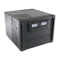
Care and Feeding an Icom PW1
W6DE
Copyright 2017, All rights reserved.
Symptom: On the PW1’s Control Panel, the AUTO indicator is Flashing and the protection circuit
cutting in.
In the PW1 Operator manual, page page 14, “Protection circuit”, “Linear amplifier protection circuit” is a
description of the various fault indications and faults. It says AUTO flashing means PA Boards have
become unbalanced. This means one of the four PA boards may be bad.
There are four PA boards; two boards on each side of the heat sink and the two PA boards on each side
of the heat sink are paired together. Then each side of the heat sink is paired in the Combiner Board.
Icom service centers do not repair boards, they replace them. The reason they might recommend to
replace all four of the PA boards is that there at least three versions of the PA board. The difference
between the boards that I’ve seen is the value and quantity of the power source swamping resistors
feeding the pair of MRF-150s. If you replace a board it is likely the new board will have different resistor
values. Thus, you also have to replace the mate board on that side of the heat sink. To be comfortable
you should also replace the pair of boards on the other side of the heat sink. If you repair your own PA
board(s), then you don’t need to replace all the PA boards.
The PA boards are sold by Icom for about $250 to $300. They are listed as a single item, but they come
as pairs—thus, for a purchase of the Icom PA board item you get two identical boards. However, the PA
boards do NOT come with the MRF-150 devices. Two MRF-150 devices are needed per PA board.
If you smelled a component cooking it could be on one of the PA boards and/or on the Combiner Board.
--The failure point on the PA boards is likely the power source swamping resistors R11 & R12. If they are
cooked, you’ll probably have to replace the MRF-150 devices on that board. Be careful replacing R11 &
R12, it is very easy to lift the PCB trace on the bottom of the card.
--If you need to repair a PA board it is also likely that you will have to replace or repair the Combiner
Board. The power imbalance that occurred when the PA board failed is likely to have cooked the
balance resistor R6 on the Combiner Board. If R6 has cooked, it will likely char the PCB under the
resistor. You must remove all this char, doing so will also remove several layers of the Fiberglas PCB
itself—reseal the PCB with MG Chemicals Super Corona Dope. When installing a new R6, I elevated the
resistor slightly above the PCB (between 1/8 and ¼ inch). The Combiner Board is around $150 from
Icom.
If you can’t find a cooked resistor, a clamp-on ammeter will tell you which pa board is bad by its idle
current being different than the others. Separate the four DC power lines at the front of the cabinet just
after you remove the case sheet metal and measure there. The red power lines loop left down behind
sheet metal [Where, if I recall correctly, the wires go through a toroid] then up, right and then pass
toward the back between brackets and then to the four PA boards. The four red wires are B+ for the PA
units. Note carefully how your wiring gets from the front to the back, I had to disassemble and
reassemble this several times to get the wires routed without pinching them or pulling on sharp corners.
NOTE: the black two wire (red and black wires inside a black casing) termination on the Combiner Board
looks likes it is a connector on the Combiner Board. That is NOT a connector attached to the Combiner
board—it won’t remove.
To remove the PA assembly you have to take out the Filter assembly and Combiner Board assembly out
first. On the left side, you also have to remove both the center and bottom cross bars and a lateral bar

 Loading...