12 440 01 4542 00
Specifications subject to change without notice.
Air
gap
here
Open
standpipeLQKLJK
PLQLPXP
for
coilor
humidifier
drain
TEE
(1/2”
CPVC
to
3/4”
PVC
adapter
from
loose
parts
bag.)
To
open
drain
&RLORUKXPLGLILHUGUDLQ
ZKHQXVHG
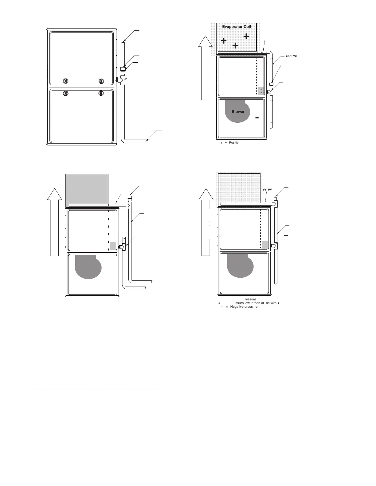
+
+
+
Condensing
Furnace
-
-
-
-
-
ÄÄÄÄÄÄÄÄÄÄ
ÄÄÄÄÄÄÄÄÄÄ
ÄÄÄÄÄÄÄÄÄÄ
ÄÄÄÄÄÄÄÄÄÄ
ÄÄÄÄÄÄÄÄÄÄ
ÄÄÄÄÄÄÄÄÄÄ
ÄÄÄÄÄÄÄÄÄÄ
Evaporator Coil
+
+
+
< +
< +
< +
+
Blower
-
3/4”
PVC
3/4
3/4
3/4
3/4
+ = Positive pressure
< + = Pressure lower than areas with +
ï = Negative pressure
+
3/4”
PVC
DIRECTION
OF
AIRFLOW
+
+
+
3/4
Open standpipeLQKLJKPLQLPXP
Air
gap
required
when
another
drain
is
connected
to
furnace
drain.
+
TEE
(1/2”
CPVC
to
3/4”
PVC
adapter
from
loose
parts
bag.)
+
+
+
Condensing
Furnace
ï
ï
ï
ï
ï
Evaporator Coil
+
+
+
< +
< + < +
+
Blower
ï
3/4” PVC
3/4
1/2”CPVCorlarger*
+
= Positive pressure
< +
= Pressure lower than areas with +
( = Negative pressure
+
3/4” PVC
DIRECTION OF AIRFLOW
+
+
+
+
3/4
3/4
3/4
3/4
Open
standpipe
(Optional
when coil drain
is
not
connected to
furnace
drain.)
Recommend “T” fitting
standpipe of same
diameteror larger
H[WHQGLQJXSZDUG
ZLWKPLQLPXPLQFKhigh
+
+
+
Condensing
Furnace
-
-
-
-
-
Evaporator
ÄÄÄÄÄÄÄÄÄ
Coil
ÄÄÄÄÄÄÄÄÄ
+
ÄÄÄÄÄÄÄÄÄ
+
ÄÄÄÄÄÄÄÄÄ
+
ÄÄÄÄÄÄÄÄÄ
ÄÄÄÄÄÄÄÄÄ
+
ÄÄÄÄÄÄÄÄÄ
< +
< +
< +
+
Blower
-
3/4”
PVC
3/4
3/4
3/4
3/4
3/4
3/4
+ = Positive pressure
< + = Pressure lower than areas with +
ï = Negative pressure
3/4”
PVC
Open
standpipe
(Optional
when
coil
drain
is
not
connected
to
furnace
drain.)
TEE
(1/2”
CPVC
to
3/4”
PVC
adapter
from
loose
parts
bag.)
DIRECTIONOFAIRFLOW
A170135
Fig. 12 -- Example of Field Drain Attachment
To Relocate the Condensate Trap:
S Orient the furnac e in the downf low positi on.
S Fig. 9 shows the condensa te tra p and tubing bef ore and after
rel oca t ion. Refer to Fig. 9 to begi n the tr ap conve r si on.
S Refer to Condens at e Dr ai n se ct i on for infor mat i on how to ins t al l the
condens at e drain.
Condensate Trap -- Horizontal Orientation.
Whe n the f urna ce is ins ta ll ed in the hori zont al right pos it i on, the
condens at e tra p wil l be initially located at the bottom of the collector
box, as received from the factory. See the top image in Fig. 10.
When the furnace is installed in the horizontal left position, the
condens at e tr ap will be initially located at the top of the collector box,
as received from the factory. See the top image in Fig. 11. In both
cas es the tr ap must be re positi oned on the col le ctor box for proper
condens at e dra i nage . See the bott om image s in Fig. 10 a nd 11.
A field--supplied, accessory Horizontal Installation Kit (trap
grom met ) is requi re d for all dir ec t--vent hori zont al insta l la ti ons ( onl y).
The kit cont ai ns a rubber cas ing gromm et desi gned to se al bet w ee n
the fur nac e ca si ng and the condens ate tr ap. Se e Fig. 18.
To Relocate the Condensate Trap:
S Remove the knoc kout i n the cas ing for the condens at e t ra p.
S Inst al l the grommet in the c as ing when requi re d for dire ct--ve nt
horiz ont al a ppl ic at ions .
S Orient the furnace in the desired position.
S Allow for 2 in. (51 mm) of cle ar anc e undernea th the fur nac e for the
condens at e trap and drai n line.
S Fig. 10 shows the condensa te tra p and tubing bef ore and after
rel oca tion in the horiz ont al right posit i on.
S Fig. 11 shows the condensa te tra p and tubing bef ore and af te r
rel oca tion in the horiz ont al lef t posit ion.
S Refer to the appropr i at e figur e to begi n the tra p conve rs ion.
S Refer to Condens at e Dr ai n se ct i on for infor mat i on how to ins t al l the
condens at e drain.
 Loading...