15
440 04 2023 02
Specifications are subject to change without notice
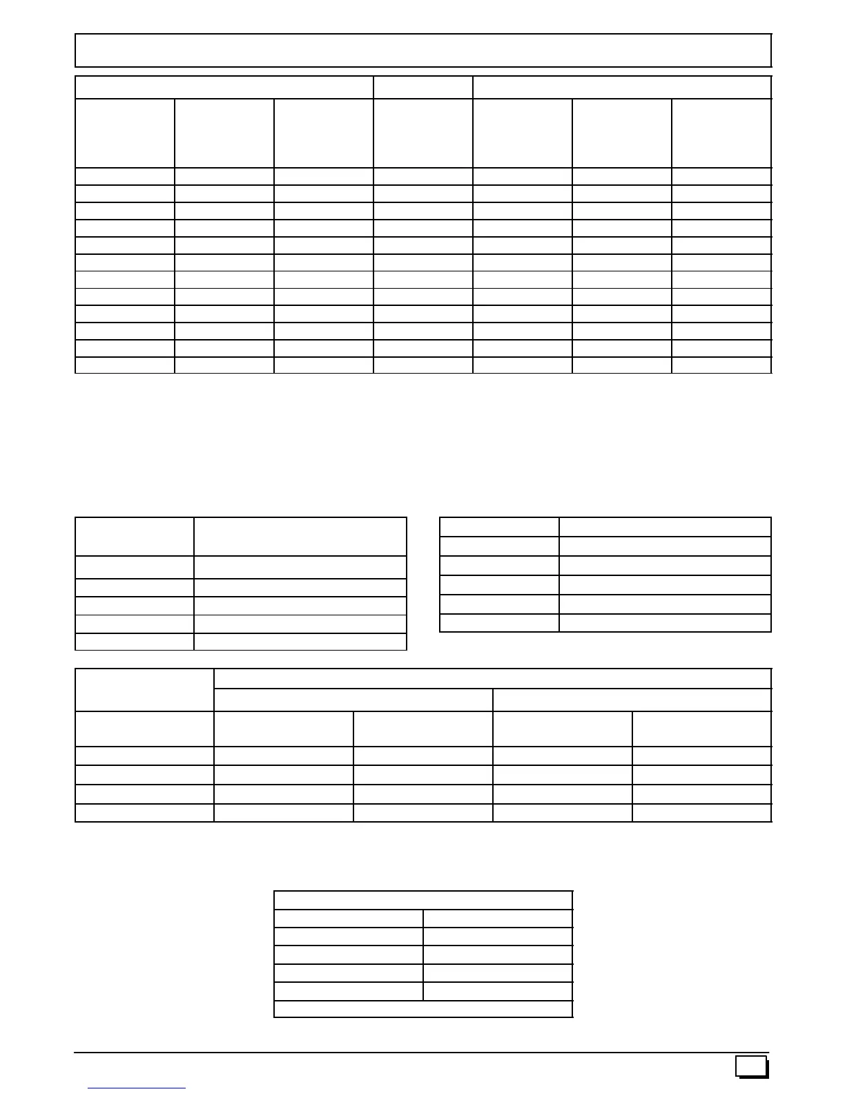
Circulation Air Blower Data - *9MPV125
Cooling CFM Adjustment Heating Rise Adjustment
DIP Switch
5&6
High Cool @
0.50 in wc
Low Cool
(80% of High
Cool)
** Adjust
Jumper
Setting
DIP Switch
3&4
High Heat
Rise Change
@0.20inwc
Low Heat
Rise Change
at Resultant
Static
00 2150 1720 + 00 -- 4 -- 4
*00 2025 1620 *NOM *00 0 0
00 1856 1485 -- 00 4 5
01 1755 1404 + 01 1 2
01 1615 1292 NOM 01 6 7
01 1452 1162 -- 01 12 13
10 1338 1070 + 10 -- 1 0
10 1201 961 NOM 10 3 4
10 1069 855 -- 10 9 10
11 909 727 + 11 -- 6 -- 6
11 800 640 NOM 11 -- 3 -- 3
11 627 502 -- 11 3 3
Airflow performance includes 1” washable filter media.
*Factory Setting
**Adjust Jumper Setting (+, NOM, --) is applied to both Cooling and Heating
Note 1: HP Mode Jumper provides a 10% reduction in airflow when in Comfort position and a call for low or high cooling is
present with the ”O” line off. This feature is to provide lower airflow for running in HP Heating Mode if desirable.
Note 2: DEHUM mode (24VAC on DEHUM terminal) provides a 20% airflow reduction during cooling calls.
Note 3: Low Heat ESP is a result of High Heat ESP (-- is decrease in rise).
Note 4: High and low heat rise values are approximate air temperature change from return air temperature when at factory
default settings.
Table 2
Continuous Fan @
0.10 in wc ESP
DIP Switch 1 & 2 Airflow (CFM)
*00 1032
01 1778
10 2178
11 2178
* Factory Setting
Table 3 SW2 DIP Assignments
DIP Switch Blower Parameter
1&2 Cont Fan Adj
3&4 Heat Speed Adj
5&6 Cool Speed Adj
7&8 Cool On/Off Delay
Table 4
Cooling Delay Options (SW2 -- 7, 8)
ON DELAY OFF DELAY
DIP SW2 -- 7/8 Timed ON (sec)
Airflow during on
delay
Timer OFF (sec)
Airflow during off
delay
*00 5 OFF 90 100%
01 5 OFF 0 OFF
10 30 50% 30 100%
11 30 50% 180 50%
Airflow % is of High Cool airflow demand determined from SW2--5/6 Table 1
Airflow resumes to 100% after on delay time is completed
Airflow stops (or switches to continuous fan speed) after off delay time is completed
* Factory Setting
MAX CFM’s for Factory Washable Filters
Dimensions Airflow (CFM)
14” x 25” 1400
16” x 25” 1600
20” x 25” 2000
24” x 25” 2500
MAX CFM based on 600 FPM
Note 1: Disposable filters are typically rated at 300 FPM. These filters only allow half the airflow when compared to 600 FPM
filters. (example, 20 x 25 @ 600 FPM = 2000CFM, @ 300 FPM = 1000 CFM)
 Loading...