SERVICE AND TECHNICAL SUPPORT MANUAL Gas Furnace: (F/G)9MAE
Specifications subject to change without notice.
440 04 4700 00 11
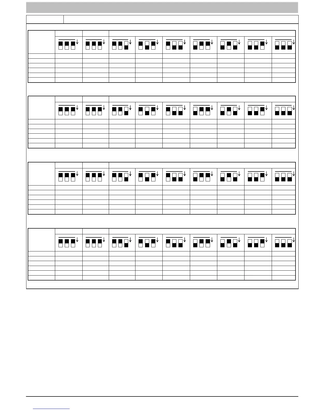
Table 3 Airflow Switch Table
OOOOOOOOO
321
N
321
N 321N 321N 321N 321N 321N 321N 321N
060-14
080-14
060-20
080-20
100-22
120-22
OOOOOOOOO
321
N
321
N 321N 321N 321N 321N 321N 321N 321N
060-14
080-14
060-20
080-20
100-22
120-22
OOOOOOOOO
321
N
321
N 321N 321N 321N 321N 321N 321N 321N
060-14
080-14
060-20
080-20
100-22
120-22
OOOOOOOOO
321
N
321
N 321N 321N 321N 321N 321N 321N 321N
060-14
080-14
060-20
080-20
100-22
120-22
NOMINAL AIRFLOW BASED ON 370 CFM/TON (SW1-5 = ON, SW4-3 = ON)
COOLING (SW2) AND CONTINUOUS FAN (SW3) AIRFLOW: SET-UP SWITCH POSITIONS
NOMINAL AIRFLOW BASED ON 325 CFM/TON (SW1-5 = OFF, SW4-3 = ON)
COOLING (SW2) AND CONTINUOUS FAN (SW3) AIRFLOW: SET-UP SWITCH POSITIONS
NOMINAL AIRFLOW BASED ON 400 CFM/TON (SW1-5 = ON, SW4-3 = OFF)
COOLING (SW2) AND CONTINUOUS FAN (SW3) AIRFLOW: SET-UP SWITCH POSITIONS
NOMINAL AIRFLOW BASED ON 350 CFM/TON (Factory Default - SW1-5 = OFF, SW4-3 = OFF)
COOLING (SW2) AND CONTINUOUS FAN (SW3) AIRFLOW: SET-UP SWITCH POSITIONS
L11F092
Adjust Thermostat Heat Anticipator
a. Mechanical thermostat. Set thermostat heat
anticipator to match the amp. draw of the electrical
components in the R−W/W1 circuit. Accurate amp.
draw readings can be obtained at the wires normally
connected to thermostat subbase terminals, R and W.
The thermostat anticipator should NOT be in the
circuit while measuring current.
(1.) Set SW1−2 switch on furnace control board to
ON.
(2.) Remove thermostat from subbase or from wall.
(3.) Connect an amp. meter as shown in Figure 5
across the R and W subbase terminals or R and
W wires at wall.
(4.) Record amp. draw across terminals when
furnace is in minimum heat and after blower
starts.
(5.) Set heat anticipator on thermostat per thermostat
instructions and install on subbase or wall.
(6.) Turn SW1−2 switch OFF.
(7.) Install blower door.
b. Electronic thermostat: Set cycle rate for three cycles
per hr.