Modular Blower
Electrical Connections
Electrical shock hazard.
Turn OFF electric power at fuse box or service
panel before making any electrical connections
and ensure a proper ground connection is made
before connecting line voltage.
Failure to do so can result in property damage,
personal injury and/or death.
All electrical work MUST conform with the requirements of local
codes and ordinances and the National Electrical Code NFPA 70
current edition.
The low voltage transformer and the fan control are standard on
all models and are prewired at the factory. Line voltage
connections are made to the heater accessory or the lugs on the
No Heat Kit.
Overcurrent Protection
The power supply wiring to the unit MUST be provided with
overcurrent protection. Governing codes may require this to be
fuses ONLY or circuit breakers.
For blower cabinets without heaters, a 15 amp circuit may be
used.
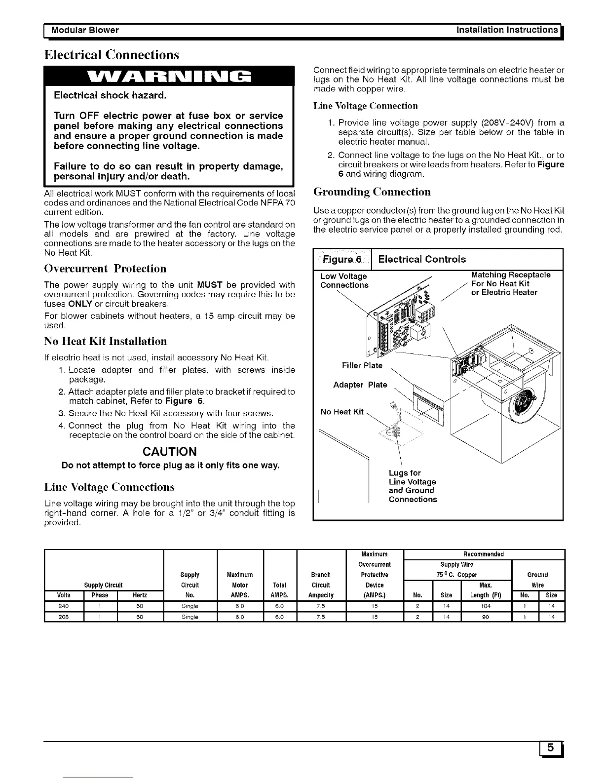
No Heat Kit Installation
If electric heat is not used, install accessory No Heat Kit.
1. Locate adapter and filler plates, with screws inside
package.
2. Attach adapter plate and filler plate to bracket if required to
match cabinet, Refer to Figure 6.
3. Secure the No Heat Kit accessory with four screws.
4. Connect the plug from No Heat Kit wiring into the
receptacle on the control board on the side of the cabinet.
CAUTION
Do not attempt to force plug as it only fits one way.
Line Voltage Connections
Line voltage wiring may be brought into the unit through the top
right-hand corner. A hole for a 1/2" or 3/4" conduit fitting is
provided.
Installation Instructions /
Connect field wiring to appropriate terminals on electric heater or
lugs on the No Heat Kit. All line voltage connections must be
made with copper wire.
Line Voltage Connection
1. Provide line voltage power supply (208V-240V) from a
separate circuit(s). Size per table below or the table in
electric heater manual.
2. Connect line voltage to the lugs on the No Heat Kit., or to
circuit breakers or wire leads from heaters. Refer to Figure
6 and wiring diagram.
Grounding Connection
Use a copper conductor(s) from the ground lug on the No Heat Kit
or ground lugs on the electric heater to a grounded connection in
the electric service panel or a properly installed grounding rod.
Figure 6 Electrical Controls
Low Voltage Matching Receptacle
Connections _ For No Heat Kit
or Electric Heater
Filler Plate
Adapter Plate
No Heat Kit
Lugsfor
Line Voltage
and Ground
Connections
SupplyCircuit
Volts Phase Her_
240 1 60
208 1 60
Supply
Circuit
No,
Single
Single
Maximum Branch
Motor Total Circuit
AMPS, AMPS, Ampacity
60 6.0 75
60 6.0 75
Maximum
Overcurrent
Protective
Device
(AMPS.)
15
15
Recommended
SupplyWire
750C. Copper
Max.
110. Size Length (Ft)
2 14 104
2 14 90
Ground
Wire
110. Size
1 14
1 14