3. Install the vent pipes as short as practical. (See Gas Vent
Installation section).
4. De NOT install furnace directly on carpeting, tile or other
combustible material other than wood flooring.
5. Maintain clearance for fire safety and servicing. A front clear-
ance of 30" (760mm) is minimum for access to the burner,
controls and filter.
6. Use a raised base if the floor is damp or wet at times.
7. Residential garage installations require:
• Burners and ignition sources installed at least 18" (457mm)
above the floor.
• Furnace must be located or physically protected from pos-
sible damage by a vehicle.
Horizontal Furnace Installation
IMPORTANT
NOTE: Inspect unit rating plate to be certain model number be-
gins with "NTC5, NTN5 or GNJ'. This identifies unit as horizon-
tally mountable. If unit does NOT bear this designation, you may
NOT mount this unit horizontally. Horizontal furnace may not be
mounted on its back.
If you purchased a horizontally mountable furnace, it can be
installed horizontally in an attic, basement, crawl space, alcove,
or suspended from a ceiling in a basement or utility room in either
a right or left airflow position. See Figure 2.
The following minimum clearances (Figure 2) to combustibles
MUST be maintained between the furnace and adjacent
construction. As shown in Figure 2, ONLY the corner of the cabi-
net is allowed to contact the rafters. All other clearances MUST
be observed as shown in Figure 1.
Figure 2 Typical Horizontal Installation
If the furnace is to be suspended from the floor joists in a crawl
space or the rafters in an attic, it is necessary to use steel pipe
straps or an angle iron frame to attach the furnace. These straps
should be attached to the furnace with sheet metal screws and to
the rafters or joists with bolts. The preferred method is to use an
angle iron frame bolted to the rafters or joists.
If the furnace is to be installed in a crawl space, consult local
codes. A concrete pad 1" to 2" (25 to 50ram) thick is recom-
mended for crawl space installation on the ground.
Thirty inches (30")(760mm) between the front ofthe furnace and
adjacent construction or other appliances MUST be maintained
for service clearance.
Keep all insulating materials clear from Iouvered door. Insulating
materials may be combustible.
The horizontal furnaces may be installed directly on combustible
wood flooring or supports, however it is recommended for further
fire protection that cement board or sheet metal is placed be-
tween the furnace and the combustible wood floor and extend 12"
(300mm) beyond the front of the furnace louver door. (This is a
recommendation only, not a requirement).
This furnace MUST NOT be installed directly on carpeting or tile
or other combustible material other than wood flooring or sup-
ports.
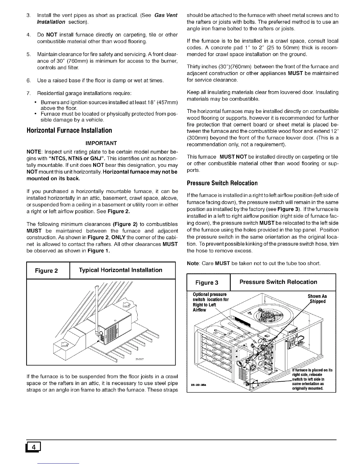
Pressure Switch Relocation
Ifthe furnace is installed in a right to left airflow position (left side of
furnace facing down), the pressure switch will remain in the same
position as installed by the factory (see Figure 3). Ifthe furnace is
installed in a left to right airflow position (right side of furnace fac-
ing down), the pressure switch MUST be relocated to the left side
of the furnace using the holes provided in the top panel. Position
the pressure switch in the same orientation as the original loca-
tion. To prevent possible kinking ofthe pressure switch hose, trim
the hose to remove excess.
Note: Care MUST be taken not to cut the tube too short.
Figure 3 Pressure Switch Relocation
Optionalpressure ShownAs
switchlocationfor
RighttoLeft
Airflow
rightside,relocate
switchto left sidein
sameorientationas
originallymounted,