OPERATING AND MAINTENANCE MANUAL
Chapter 7 - Electronic controller
iC 215 ÷ iC 780
48
The data in this manual are not binding and they can be modified by the manufacturer without notice. Reproduction of this manual is strictly prohibited
ENGLISH
EN
7.14.8 Compressors starting time limitation
If there are several compressors in a circuit but only one is running, after programmable running time the compressor is
stopped and another compressor is started (the first free compressor in accordance with the running hours or number of
starts).
7.15 Unloading function
This function makes it possible to reduce cooling capacity of the unit when required; it may affect the entire unit or a single
circuit and it is achieved by stopping one or more compressors. The unloading types are as follows:
• Unloading due to high temperature: having defined an unloading set and differential, if the temperature
measured by the probe remains above the set for an activation time, in each circuit one compressor is stopped.
If the temperature of the probe becomes lower than or equal to an unloading set less the differential, or if the
associated maximum duration has elapsed, the unloading function is deactivated and the compressors are
restarted.
• Unloading due to high pressure (if high pressure transducer is present): having defined a set, a differential
and an unloading time, if the condensing pressure measured in a circuit is greater than or equal to the set the
unloading function is activated in the circuit and then a compressor is stopped in only the circuit involved.
The unloading function is deactivated only if the condensing pressure decreases and remains below the
unloading set for a preset time or if it falls below set - diff.
7.16 Anti-freeze heaters
The anti-freeze heater is optional and can be installed on each unit only on request.
The heater ensures protection of the evaporator and the pump (if installed) against the risks of freezing when ambient
temperature falls.
The heater is of the wire resistance type and it is wrapped around the tank and pump (if installed).
Activation of the heaters is managed via the electronic controller.
The wire heaters are switched on according to the ambient temperature detected by the probe located in the fans compartment
behind the electrical panel.
Activation of the heaters is performed by way of an ambient temperature probe.
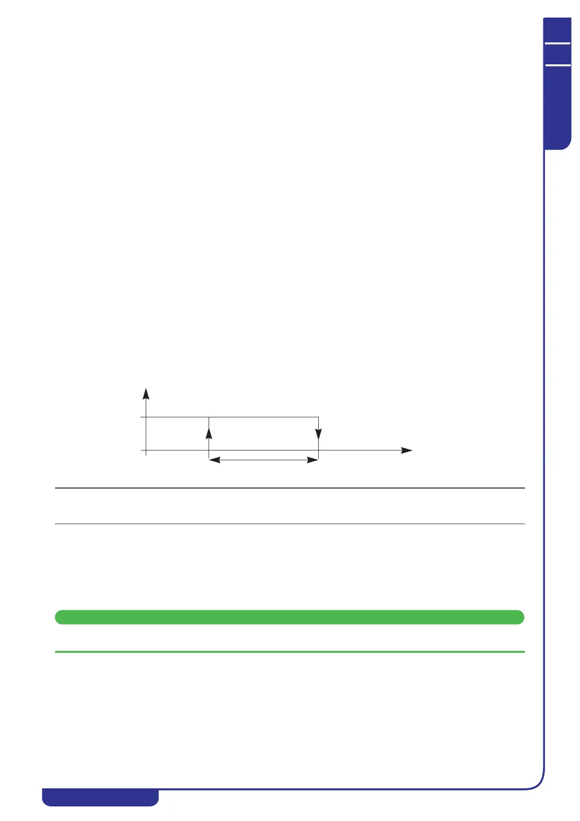
The activation logic of the heaters is described below.
The anti-freeze heater option protects components of the hydraulic circuit for ambient temperatures down to -10°C.
For lower ambient temperatures the circuit must be filled with a glycol anti-freeze product.
7.17 Fans control
On iC units the fans can be controlled in the following ways:
• ON/OFF
• by steps
• with speed control.
The selection is made on the basis of the unit configuration.
The speed control is not installed in dual frequency models.
7.17.1 Units configured with “STEP” fans
(only models iC 640÷780)
These units are equipped with a pressure transducer located on the refrigerant compressor discharge pipeline.
On the basis of the pressure read by the transducer, the electronic controller manages operation of the fans according to
ON-OFF logic, i.e. supplying or disconnecting power to the fans.
Heater status
ON
OFF
Ar2
Pb5 (BAT)
Ar1