OPERATING AND MAINTENANCE MANUAL
Chapter 7 - Electronic controller
iC 215 ÷ iC 780
32
The data in this manual are not binding and they can be modified by the manufacturer without notice. Reproduction of this manual is strictly prohibited
ENGLISH
EN
7.2.1 Function of combined buttons
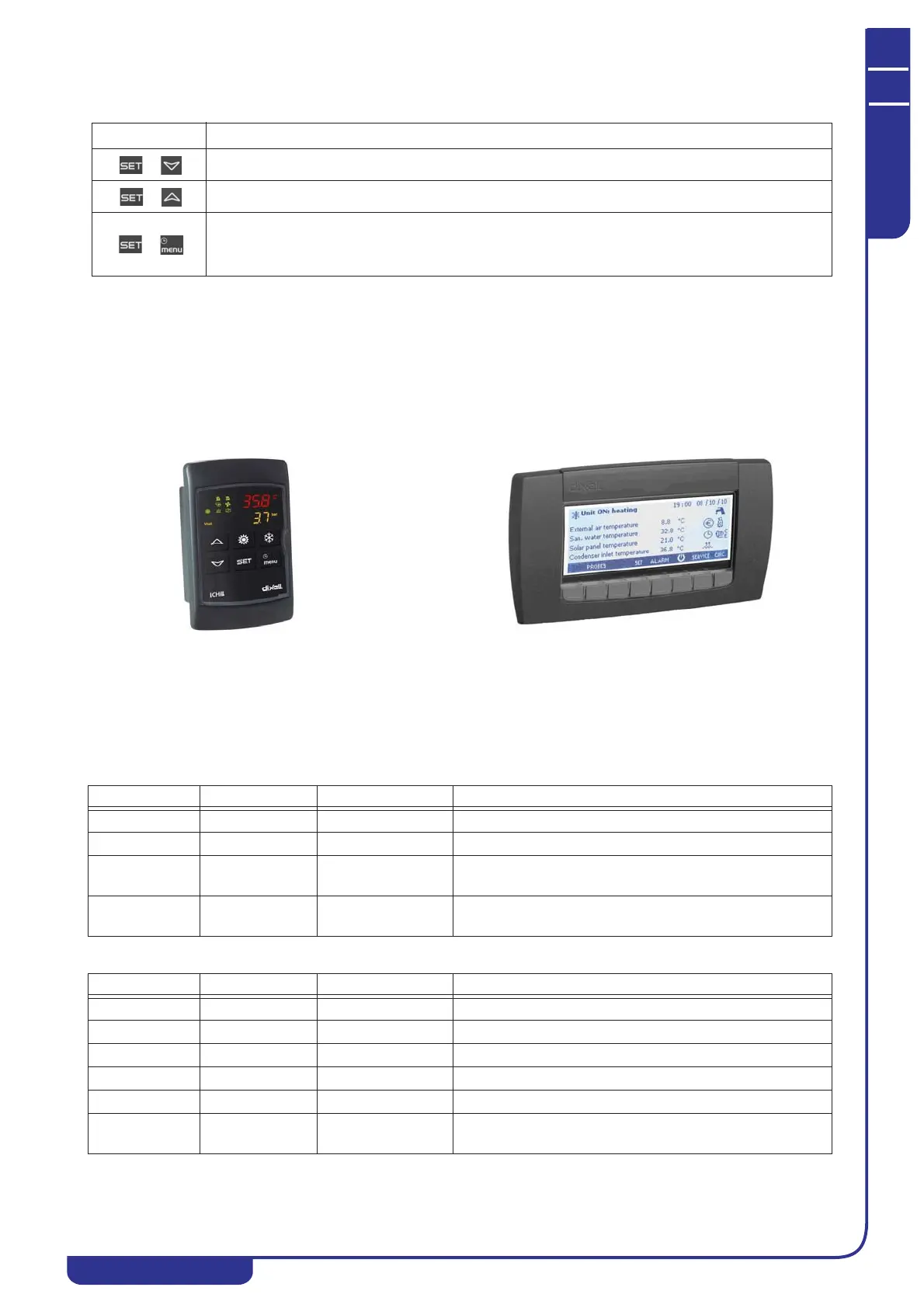
7.3 Remote terminal
Up to two remote terminals can be connected to the instrument.
The terminal generally shows the same parameters as the local display. The display can be customized with the dedicated
parameters (see “7.22 Parameters description-settings”)
In the absence of communication between the control unit and the remote terminal the upper display shows the message
“
OP-” (no link).
7.4 Probes key
This chapter refers to the BEWIT, BEWOT,BWOT, BHP1, BAT1 and BTWOT probes; for the positioning of these probes
consult the refrigerant circuit diagram and the electrical diagram.
Descriptions of the probes utilised are given below
Models iC 215÷540:
Models iC 640÷780:
BUTTONS FUNCTION
+
To enter programming mode (pressed for 3 seconds).
+
To exit programming phase.
+
In programming mode:
Press once from the main mask to display the “user” parameters;
Press twice from the main mask to display the “service” parameters.
Duplicate remote control with LED display.
Semi-graphic remote control with LED display.
Probe code Board label Board terminals Description
BTWOT EOut PB1 Tank water outlet temperature probe (temperature control)
BEWOT Out1 PB2 Evaporator water outlet temperature probe (anti-freeze)
BCP1 CdP1 PB3 Circuit 1 high pressure temperature transducer (only with
electronic control)
BAT1 Et PB6 Ambient temperature probe (only with anti-freeze heater
option)
Probe code Board label Board terminals Description
BTWOT EOut PB1 Tank water outlet temperature probe
BEWOT1 Out1 PB2 Evaporator 1 water outlet temperature probe
BHP1 CdP1 PB3 Circuit 1 high pressure transducer
BHP2 CdP2 PB4 Circuit 2 high pressure transducer
BEWOT2 Out2 PB5 Evaporator 2 water outlet temperature probe
BAT1 Et PB6 Ambient temperature probe (only with anti-freeze heater
option)