OPERATING AND MAINTENANCE MANUAL
Chapter 1 - General information
iC 215 ÷ iC 780
6
The data in this manual are not binding and they can be modified by the manufacturer without notice. Reproduction of this manual is strictly prohibited
ENGLISH
EN
CHAPTER 1
GENERAL INFORMATION
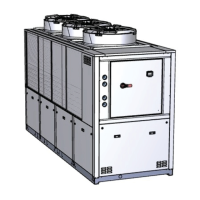
The units described in this manual may be referred to below as “WATER CHILLERS”
This manual is addressed to personnel responsible for installing, using and servicing the unit.
The units were constructed using components made by premium quality manufacturers and the entire design, production and
control process was carried out in compliance with standard ISO 9001.
In the majority of applications the liquid in the user circuit is water so henceforth the term “WATER” will be utilised, even if
the liquid in the user service is different (for example mixtures of water and ethylene or propylene glycol).
Hereinafter the expression “PRESSURE” is used to indicate relative pressure.
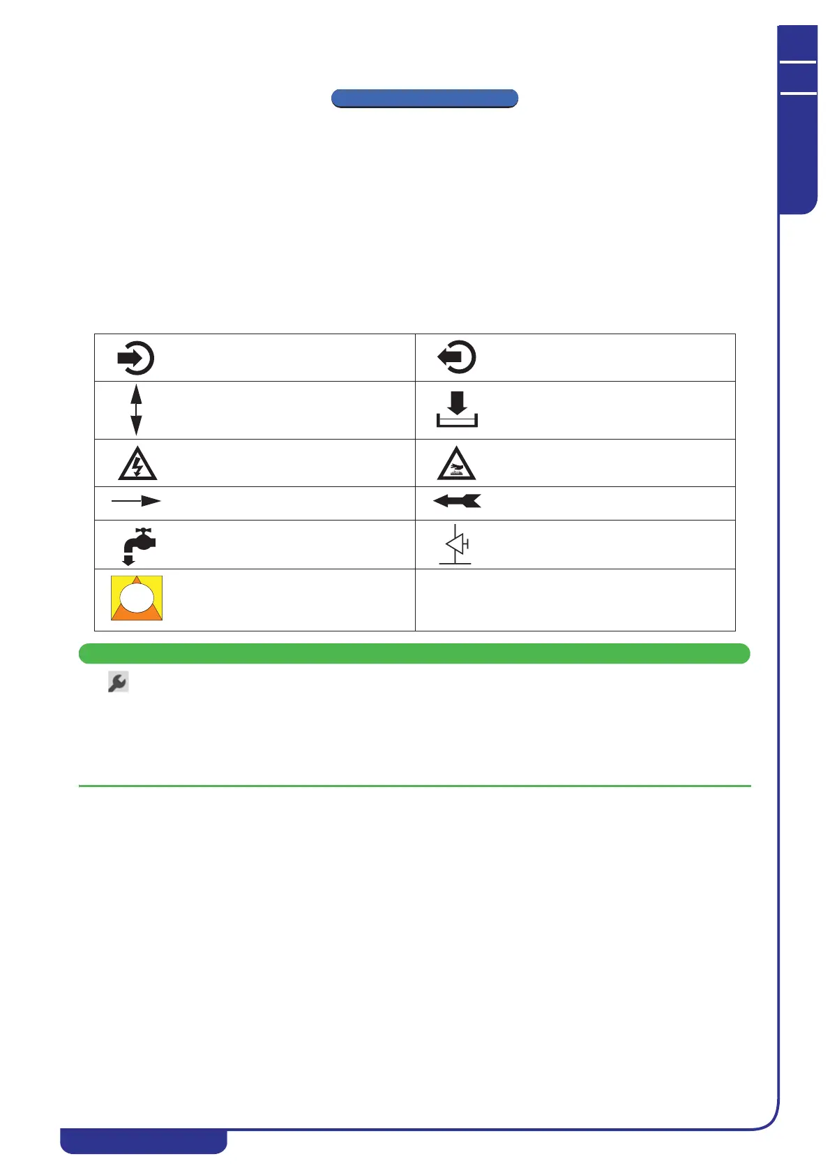
The following symbols are to be found on the decals affixed to the unit and also in the dimensional drawings and refrigerant
circuit diagrams.
The meaning of each symbol is indicated below:
This manual, which is addressed to users, installers, and service personnel, supplies all the technical information
required to install and work with the unit and to perform the routine maintenance operations required to maximise its
working life.
Use only genuine parts when carrying out routine maintenance or repairs.
Requests for SPARE PARTS and any INFORMATION concerning the unit must be made to your dealer or nearest service
centre, specifying the MODEL and SERIAL NUMBER shown on the unit’s dataplate and on the last page of this manual.
Process water inlet Process water outlet
Indication of the axis of reference for lifting
operations
Drain point to empty the unit of water
Electric shock hazard
Risk of burns from contact with high-
temperature surfaces
Direction of flow of refrigerant fluid and
water circuit
Rotation direction of pump (if installed) and
fans
Water filling point Air bleed valve
Opening to be used for the insertion of
bars for the purpose of lifting the unit