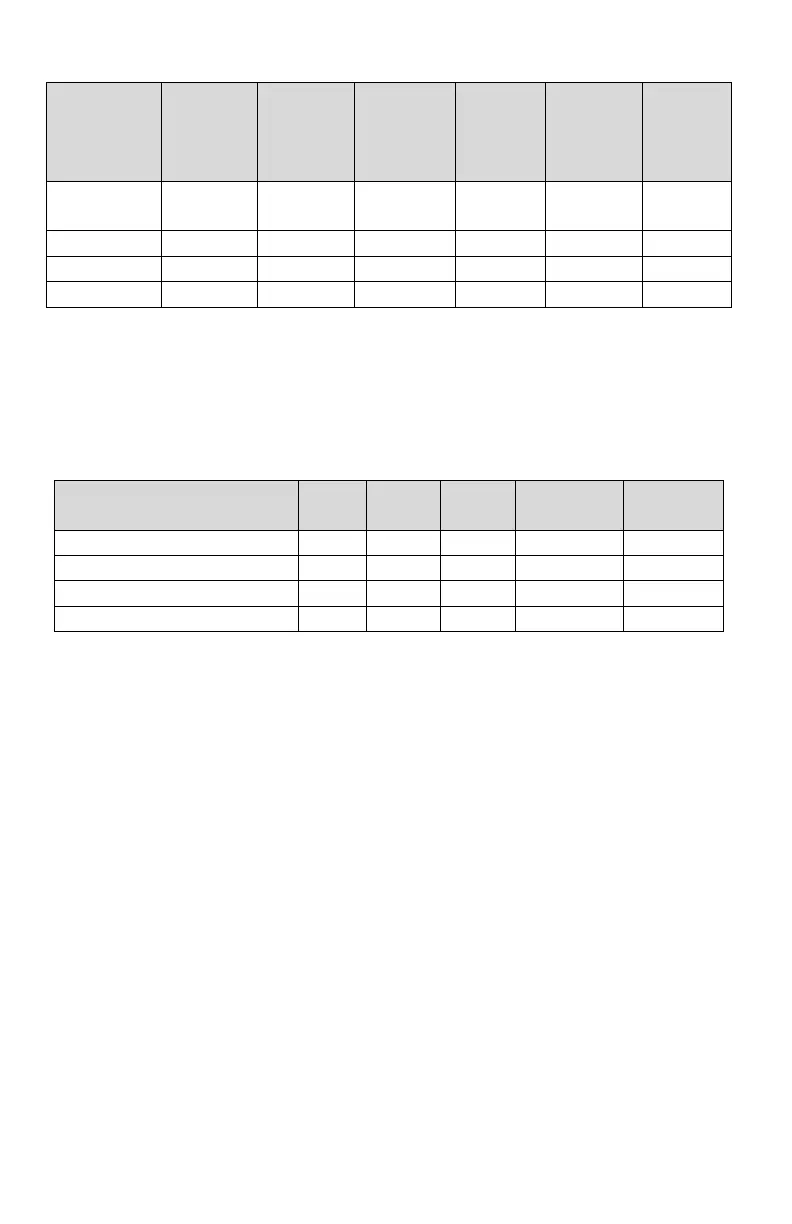
Maximum Charge Current – Switch Settings (1 = UP, 0 = Down)
• Set the low voltage disconnect (LVD) disconnect and reconnect voltage
points, by setting SW 1, and SW 2 on the back panel according to the
following chart:
LVD Disconnect/Reconnect V – Switch Settings (1 = UP, 0 = Down, x = either)
INSTALLATION
Mount the unit in a standard 19 inch equipment rack, (ensuring side air vents are
not blocked) using rack mounting screws (not supplied), then make the following
connections using wire and connectors appropriately rated for the maximum input
and output current rating of the unit:
• Remove the plastic bus bar cover by removing the two screws holding it in
place
• Connect the supply POS output bus bar to the load positive input (using a
supplied bus bar bolt/washer/nut set for the bus bar connection) (NOTE: do
not connect the load directly to the battery, as this will defeat the battery
charging and low voltage disconnect functions)
• Connect the supply NEG bus bar to the load negative input terminal (using a
supplied bus bar bolt/washer/nut set for the bus bar connection)
• Connect a ground bonding wire from the chassis ground stud to the rack