Home
ICT
Controller
Protege GX
ICT Protege GX - User Manual
6 pages
Manual
Summary
Specs
Ask a question
Save Page as PDF
To Next Page
To Next Page
Loading...
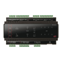
PRT-CTRL-DIN
1. Introduc
t
Thank you for
p
System Control
is the central pr
o
with all system
information, pr
o
alarms and sys
t
computer.
When receiving
the kit contains
have the corre
c
immediately.
y
Protege G
X
y
18 1K oh
m
y
1 330 Oh
m
y
1 Diode 1
N
y
DIN Rail
M
For more infor
m
Controller and
o
login to www.in
c
Protege GX
D
Integrated Syste
m
Quick Star
t
t
ion
p
urchasing the Proteg
e
ler by Integrated Con
t
o
cessing unit of the P
r
modules, stores all c
o
o
cesses all system co
m
t
em activity to a moni
t
g
the GX Integrated S
y
the items listed belo
w
c
t contents, you shoul
d
X
DIN Rail Integrated
m
resistors
m
EOL Termination R
e
N
4007 1A 400V (Axial
M
ounting Strip
m
ation on the Protege
o
ther Integrated Cont
r
c
ontrol.co.nz.
D
IN Rail
m
Controlle
r
t
Guide
e
GX DIN Rail Integra
t
rol Technology. The
C
r
otege System. It com
m
o
nfiguration and trans
a
m
munication, and rep
o
t
oring station or remot
y
stem Controller you
s
w
. Please note that if y
d
contact your distribu
System Controlle
r
e
sisto
r
)
GX DIN Rail Integrat
e
r
ol Technology produ
c
ted
C
ontroller
m
unicates
a
ction
o
rts
e
s
hould find
ou do not
tor
e
d System
c
ts please
T
D
c
o
P
s
a
w
e
x
b
m
m
I
n
f
o
T
R
A
d
L
d
T
o
2. Powe
r Re
quir
e
T
he Prote
ge
GX Integr
D
C po
w
e
r suppl
y conn
o
ntain internal r
egulat
P
RT-PSU
-DIN is
used
a
me pow
e
r
supply
ca
n
w
ell, so long as t
he m
a
x
ceeded. If
using the
ackup and can be co
n
m
onitored suppl
y. Ple
a
m
anual for specific det
a
Exam
p
n
larger installations, t
h
o
r load sharing
bet
w
e
e
Exam
p
3. Card Re
ade
r
C
T
he follo
w
i
ng dia
g
ram
R
eader w
i
th the GX
In
t
A
ccess Door
in Entry
o
ual LED read
er
mode
ED mode. Ref
e
r to
y
o
etails.
PRT-CTRL-DIN
NA
N+
N-
NB
o
other modules
on network
Module #3
NA
N+
N-
NB
Power Supply #3
e
ments
r
ated S
y
ste
m
Controll
e
ected to the
N+ and
N
ion or isolation. It is r
e
for this pur
pose. In a
n
be used t
o
suppl
y
t
h
a
ximum loa
d
of the po
w
PRT
-
PSU-
D
IN modul
e
n
nected to t
he modul
e
a
se refer to t
he PRT-P
a
ils of the connection
s
p
le Powe
r
Supply Co
n
he po
w
e
r suppl
y
ma
y
e
n sever
a
l
supplies.
p
le
m
u
ltiple PSU Con
C
on
ne
ction
sho
w
s the
connectio
n
t
eg
rated S
ystem Cont
r
o
r Exit mo
de
. The Con
and r
eader
s must be
o
u
r
card
rea
der docu
m
NA
N+
N-
NB
Gel Cell Backup Battery
+
-
V1+
V
1+
V1+
V
1+
V
1
Module
#
N
A
N+
N-
Module #2
NA
N+
N-
NB
Power Supply #2
e
r is supplied b
y
a 12
V
N
- t
e
rmi
nals. It does n
o
commended that a
n
I
C
s
mall i
n
stallation this
h
e mod
u
le net
w
o
rk as
w
er su
ppl
y
is not
e
, it ca
n support batte
e
net
w
o
rk to provide a
S
U
-
D
IN installation
s
.
n
nection
need t
o
be split to all
o
n
ection
of a standard Wiega
n
r
oller c
ontrolling an
troller
does not supp
o
configured for
single
m
entati
on for fu
rther
B+
B-
LN
PRT-PSU-DIN
V1+
V-
1
+
V-
V-
V-
V-
V-
Mains Input
#
1
PRT-CTRL-DIN
NA
N+
N-
NB
A
NB
Power Supply #1
V
o
t
C
T
ry
o
w
n
d
o
rt
4. Do
o
The Prot
e
of up to
4
doors. E
a
that is a
u
The follo
w
door pos
and Alar
m
Inpu
t
Inpu
t 1
Inpu
t 2
Inpu
t 3
Inpu
t 4
Inpu
t 5
Inpu
t 6
Inpu
t 7
Inpu
t 8
Card Re
a
o
r Co
ntact
Conn
e
e
ge
GX Integrated S
y
4
contact
s
for monitor
i
a
ch inpu
t on the
Cont
r
u
tomatically
assigned
a
w
ing example show
s
t
ition monitoring conta
c
m
conditions of the d
o
Door Co
n
Func
tio
n
Door Conta
c
t, Po
r
REX In
put,
Port 1
Bond Se
nse
,
Por
t
R
E
N
Inpu
t,
Por
t
1
Door Conta
c
t, Po
r
REX In
put,
Port 2
Bond Se
nse
,
Por
t
R
E
N
Inpu
t,
Por
t
2
Sh
Shiel
d
RED
BLACK
GREEN
WHITE
ORANGE
BROWN
BLUE
YELLOW
SHIELD
N/R
N/R
Shield not
connected
V+
V-
Z4
V-
Z3
Z2
V-
Z1
a
der Co
nnection
e
c
t
ion
y
stem Contr
o
ller
allow
s
ng
and controlling ac
c
r
olle
r can be used
for
t
a
n
d
as a normal inp
u
t
t
he
connection of a n
o
c
t to monitor the Op
e
n
o
or.
n
tact Co
nnection
Default S
e
r
t 1
Door Conta
c
t
R
EX In
put
,
P
o
1
General
Pur
p
General
Pur
p
r
t 2
Door Conta
c
t
R
EX In
put
,
P
o
2
General
Pur
p
General
Pur
p
ield is frame
gr
ounded at
one point
d
ed Cable
Z4
V
-
BZ
L1
D1
DO
N.C. Input Contact
N.C. Input Contact
N.O. Input Contact
N.O. Input Contact
1K
1K
1K
1K
1K
1K
1K
1K
s
the conn
ection
c
ess contr
o
l
t
he doo
r functio
n
t
on the s
y
stem.
o
rmall
y
closed
n
, Closed, Forc
ed
e
tting
, Port
1
o
rt 1
p
os
e I
n
p
u
t
p
os
e I
n
p
u
t
, Port
2
o
rt 2
p
os
e I
n
p
u
t
p
os
e I
n
p
u
t
V+
V-
-
Z3
Z2
V-
Z1
Door Contact
Bond Sense
REN Input
REX Input
2
Need help?
Do you have a question about the ICT Protege GX and is the answer not in the manual?
Ask a question
Summary
Introduction to Protege GX Controller
Page: 1
Protege GX Power Requirements and Supply
Page: 2
Connecting Card Readers to Protege GX
Page: 2
Door Contact Connection Guide
Page: 3
Lock Output Configuration and Wiring
Page: 4
Encrypted Module Network Communication
Page: 4
Ethernet Interface Setup
Page: 4
Telephone Dialer Functionality
Page: 5
Protege GX Input Monitoring
Page: 5
Protege GX Technical Specifications
Page: 6
ICT Protege GX Specifications
Print Specification
General
Model
Protege GX
Operating Voltage
12VDC
Input Voltage
12VDC
Communication
RS-485
Compatibility
Protege
Communication Ports
Ethernet, RS-485
Related product manuals
ICT Protege WX
21 pages
ICT Protege SE
62 pages
ICT PRT-WX-DIN
153 pages
ICT PRT-CTRL-DIN-IP
70 pages