Do you have a question about the ICT Protege SE and is the answer not in the manual?
Explains the conventions used in the document for clarity and understanding.
Lists standards and codes the equipment must be installed in accordance with for compliance.
Provides step-by-step instructions for mounting the Protege Controller board within an enclosure.
Details cabinet options for UL/ULC Central Station Fire Monitoring and Electronic Access Control Systems.
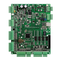
Illustrates the main connection diagram for the Protege SE Integrated System Controller.
Provides guidelines and cautions for correct wiring, tamper switch, and earth ground connections.
Details AC power requirements, transformer specifications, and battery backup connections for reliable operation.
Explains encrypted RS-485 module network setup, telephone dialer, expansion connector, and Ethernet interface.
Details connecting Wiegand readers and door contacts for access control and door status monitoring.
Explains lock output connections and programming the onboard reader for access control functions.
Explains the 16 zone inputs, their monitoring capabilities, and resistor value options.
Details the 64 local trouble zones used for monitoring system status and fault conditions.
Describes Bell/Siren PGM outputs and PGM 3/4 outputs for alarms, sirens, and general functions.
Explains the use of reader PGMs for controlling reader-specific functions like LEDs and beepers.
Details DIP switch functions and the procedure for resetting the controller to factory defaults.
Explains the meaning of various LEDs on the controller for status, faults, power, and communication.
Provides diagrams showing component layout, connections, and physical dimensions of the controller.
Lists system capacities for various profiles like Standard, Access, Elevator, School, Storage, Automation, and Apartment.
Details operating voltage, current, temperature, humidity, dimensions, and weight.
Provides examples and validation checks for current consumption and transformer usage.
Specifies maximum total output current for standby operation to comply with UL and ULC standards.
Details compatibility, ULC, and UL compliance requirements for system installation.
Outlines FCC Part 15 rules and Industry Canada compliance for digital apparatus.
Provides product codes for ordering and details the two-year warranty for defects.
Offers contact details, website, and toll-free numbers for Integrated Control Technology support.
| Brand | ICT |
|---|---|
| Model | Protege SE |
| Category | Controller |
| Language | English |