16 PRT-CTRL-SE Protege SE Integrated System Controller Installation Manual | June 2017
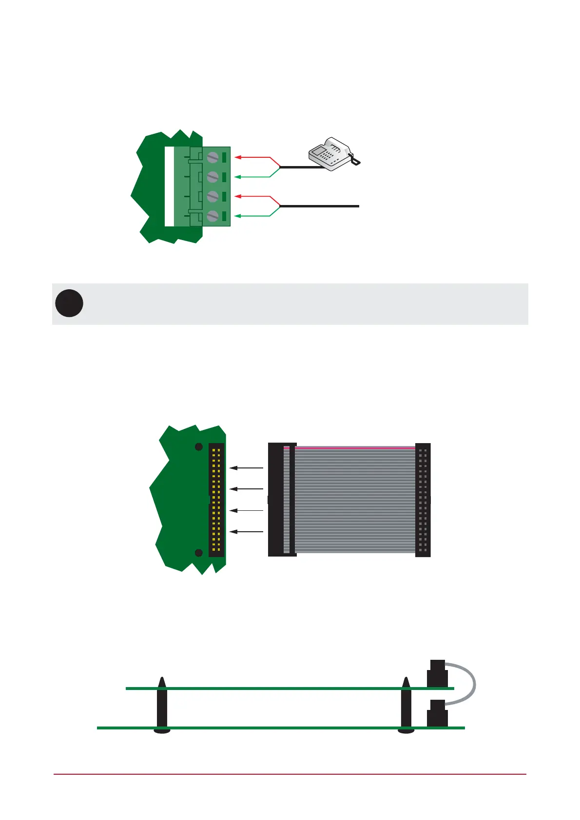
4.10 Telephone Dialer
The Controller provides the ability to communicate alarms and upload/download information with remote
systems using the onboard 2400bps modem. The telephone line can be connected directly to the Controller
using the onboard telephone connection terminals.
Telco line p and ring input
Telco line out
T1i R1i T1o R1o
Telephone Line Connection
UL
ULC
For UL/ULC installations, a Modem Surge Protection Interface must be used.
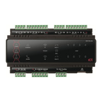
4.11 Expansion Connector
The Controller has an onboard expansion connector that is used to connect serial communication, memory and
special function interface devices. Connect the interface card to the Controller as shown in the following
diagrams. For configuration information, refer to the Protege Reference Manual and the installation instructions
provided with the interface device.
Expansion Connector and Mounting Hole Location
When installing the daughter board, ensure that the plastic mounting hardware provided is correctly inserted
from the rear of the Controller. Pay attention to the key location of the 40 Way connector.
Daughter Board
Main System Controller
40 Way
Expansion Connector
Connection and Mounting