PRT-CTRL-SE Protege SE Integrated System Controller Installation Manual | June 2017 27
7 Programmable Outputs
The Controller has 8 programmable outputs (PGMs). The PGMs are used to activate sirens, bells, warning
devices, control lighting and doors. The first 2 PGMs on the Controller have special hardware designs that
allows them to monitor for fault conditions and are ideally suited to driving sirens and warning devices.
7.1 Bell/Siren PGM Outputs
The + and - terminals of Bell 1 (PGM1 CP001:01) and Bell 2 (PGM2 CP001:02) are used to power bells, sirens
or any devices that require a steady voltage output. The bell outputs supply 12VDC upon alarm and support
one 30-watt siren. The bell output uses a electronically fused circuit and automatically shuts down under fault
conditions.
UL
ULC
Not investigated by UL/ULC for Local Burglary applications
B1+ B1- B2+ B2- P1 P2
+
-
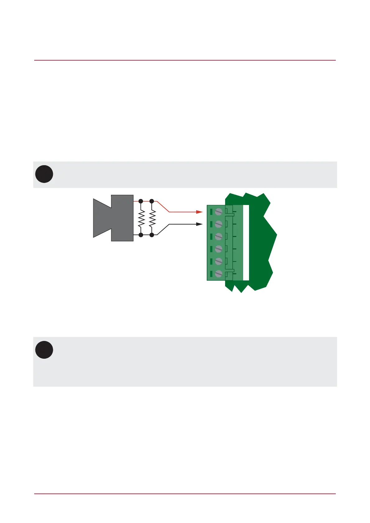
12VDC siren
warning device
1k Resistors
Bell Siren PGM 1/2 Connection
If the load on the bell terminals returns to normal, the Controller reinstates power to the bell terminals on the
next transition of the output.
i
When the bell output is not used, the appropriate trouble zone will be activated (refer to the
section on Trouble Zones (see page 26)). This can be avoided by connecting a 1K resistor
(provided in the accessory bag) across the bell output. If the bell is not being used for another
function, and the trouble zone is not programmed in the system, a resistor is not required.
Connecting a Piezo siren may result in a dull noise being emitted. This is caused by residual
current from the monitoring circuit. To prevent this occurring, connect 2 1K resistors in parallel.