PRT-CTRL-SE Protege SE Integrated System Controller Installation Manual | June 2017 29
8 Hardware Configuration
8.1 Configuration Switch
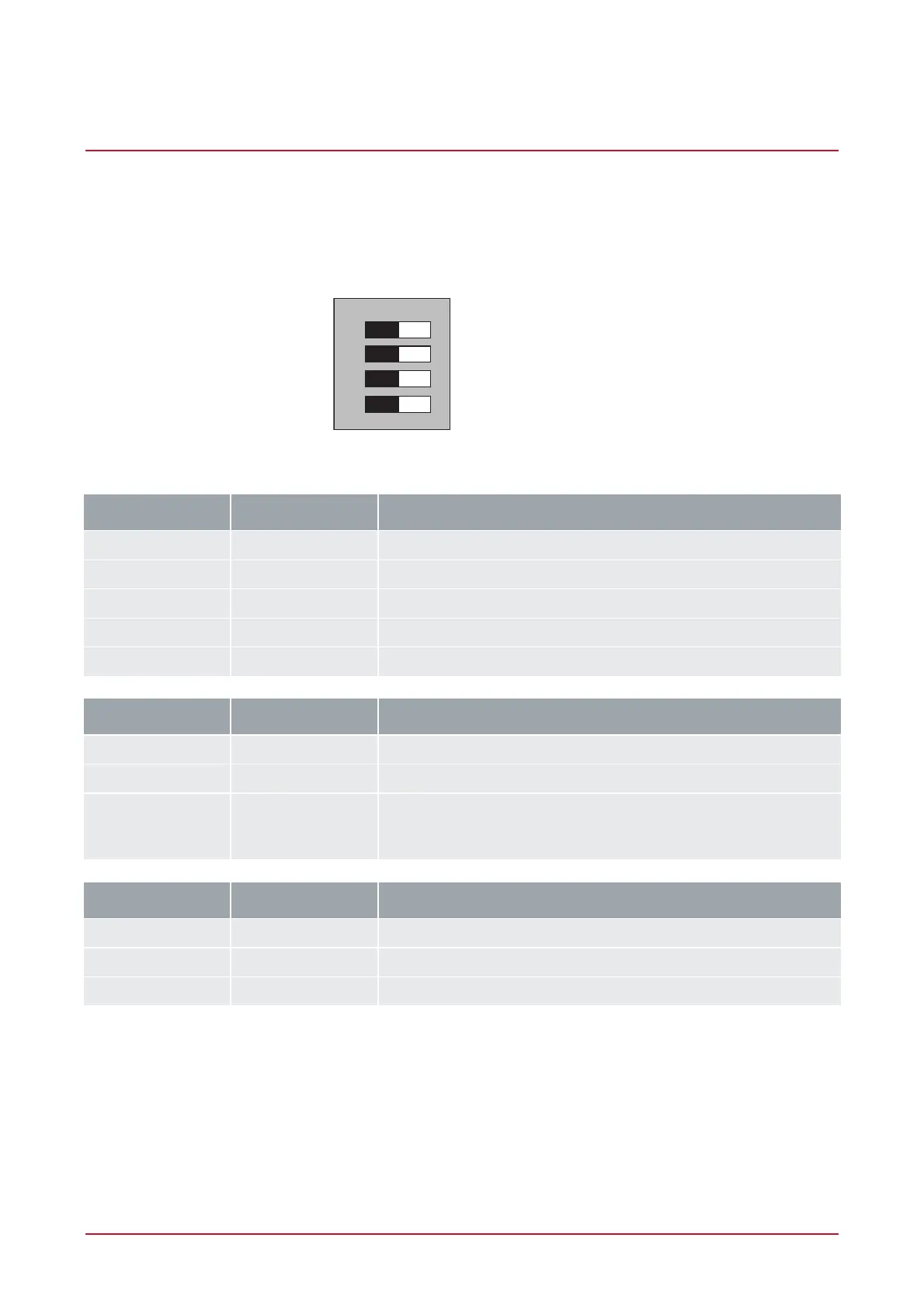
The Controller uses a 4 way dual inline dip switch located in the centre of the PCB board. This switch is used to
configure the boot up and power on settings for the Controller. Each of the switch positions performs a different
function. For normal operation, all switches shall be in the off position.
BOOT MODE 1
BOOT MODE 2
BIOS COMMUNICATION
DEFAULT CONTROLLER
1
2
3
4
ONOFF
Configuration Switch
Switch Switch Function
1 2 Power Up Boot Mode
OFF OFF Normal Operation
ON OFF BOOT Loader
OFF ON BIOS Utility
ON ON Reserved Do Not Set
Switch Switch Function
3 - IP Address Configuration
OFF - Programmed IP Configuration
ON - IP will be set to 192.168.111.222 while this switch remains on.
Allows the connection and review of the programmed IP address or
the modification to another setting.
Switch Switch Function
4 - System Default
OFF - Normal Operation
ON - Factory Default Protege Controller