PRT-CTRL-SE Protege SE Integrated System Controller Installation Manual | June 2017 31
9 LED Indicators
The Controller includes extensive diagnostic indicators that can aid the installer in diagnosing faults and
conditions. In some cases an indicator may have multiple meanings depending on the status indicator display.
9.1 Status LED
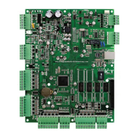
The Status indicator is located in the centre of the PCB and indicates the status of the Controller. If the
Controller is operating normally the LED will indicate this by flashing at 1 second intervals.
9.2 Fault Indicator
The Fault indicator is located in the centre of the PCB. During normal operation the fault indicator is off. Flashing
on will indicate that the Controller is operating in firmware update mode and requires firmware to be
downloaded.
9.3 Charge/Test Indicator
The Charge/Test indicator serves two functions. It indicates that a battery test is in progress and also that
battery charging is being performed. When AC is present, the battery charging current will be indicated by a
varying intensity level on this indicator. This indicator will also illuminate when a battery test is in progress by
illuminating brightly for 30 seconds every 10 minutes. The battery test period is a programmable option in the
Controller system options.
This LED is identified by the text CHARGE/TEST. This indicator does not function when AC is not present.
9.4 Auxiliary OK Indicators
Auxiliary voltage is supplied to the AUX1 and AUX2 outputs through two separate auxiliary fuses. If auxiliary
supplies are normal, both the AUX1 OK and AUX2 OK indicators will be illuminated.
9.5 AC OK Indicator
When a valid AC input is provided to the Controller the AC OK indicator will illuminate.
9.6 5V Isolated Power Indicator
The module communicates using an isolated RS-485 interface for optimal performance and this requires an
isolated supply on the N+ and N- terminals of the module network interface. When a valid supply is input, the 5V
ISO indicator will illuminate.