5 VDV II Pro 158802.02
CABLE TESTING
To test a cable:
• Connect the cable to the tester and to a suitable Remote Unit as described above.
o Cable testing runs continuously (except when in TOOLS mode or if voltage
detected). There is no need to start or stop the cable test.
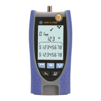
Cable test results are shown using the two rows of numbers in
the lower half of the
display. The top row of numbers refers to the pins at the near end. The numbers
displayed, and S (Shield),
depend on the port in use…
– Pins 1, 2, 3, 4, 5 and 6 are shown
– S and Pin 1 are shown
– Pins 1, 2, 3, 4, 5, 6, 7 and 8 are shown. S is shown if the shield is connected.
The lower row of numbers refers to the pins at the far end. The n
umbers displayed show
which pin at the far end is connected to which pin at the near end. Open circuits and short
circuits are
shown. Multiple short circuits are shown in sequence.
! next to the Split Pair symbol shows when the test is disabled.
o When the Split Pair test is enabled, split pairs will cause the test to fail.
o When the Split Pair test is disabled, split pairs will not cause the test to fail.
To disable / enable the Split Pair test:
• Press and hold the port selection button of the currently selected port for 2
seconds to change the setting.
o The Split Pair test is disabled or enabled.
Test Failed
Passed
Shows that Shield and Pins
1, 2 and 3 are correctly
connected
Shows that Pin 6 is
connected to Pin 7
Shows that Pin 8 is
disconnected
Shows when Split Pair
test is disabled
Shows that Pins 6 and 7
are short circuit
Shows when a crossover (uplink
cable) is detected (does not cause
Pin 5 are reversed
Flashes when Split
Pair is detected
 Loading...