- 5 -
The thermostatic mixing valve must be installed in such a position that maintenance of the TMV and its
valves and the commissioning and testing of the TMV can be undertaken.
1. The Thermostatic mixer can be installed with rear, rising or falling supply inlets. Decide on the most
appropriate method of your installation, and rotate the elbows to suit.
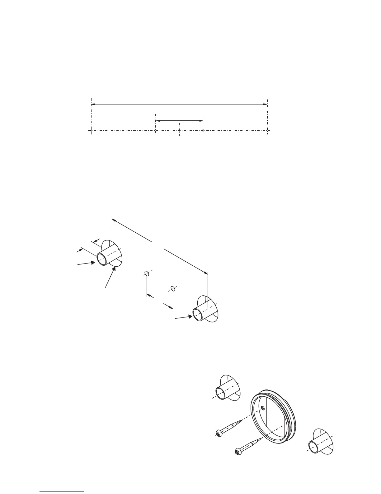
2. Mark horizontally the positions of the holes for the backplate and pipe centres on the finished wall
as shown
150
41
6. Fit the supply pipework: Hot on the Left / Cold on the right. The inlet pipework should extend 32mm
(+/-1mm) from the finished wall surface.
7. Remove the backplate from the mixer by loosening the grubscrew with a 2.5mm hexagonal key
(supplied). Secure the mounting bracket to the wall
with the screws and plugs provided.
3. For exposed rising or falling supplies the pipe positions should be set 43mm from the centre of
pipe to the finished wall at 150mm centres. Note if replacing an existing installation with pipework
centres between 147mm and 155mm a universal retrofit accessory kit is available A5526AA
4. For solid walls drill the holes for the backplate with a 6mm drill and insert the wall plugs (supplied).
For other types of wall structure alternative fixings may be required (not supplied)
5. For rear entry supplies only. Drill the holes for the supply pipes at 150mm centres.
Note!
Recess the inlet holes Ø33mm x 12mm deep to allow for the concealing plates.
32
150
41
Recess depth
Ø33mm x 12mm
INSTALLATION GUIDE
4
hot
cold
Figure 6
Figure 7
Figure 5
 Loading...