EasyManua.ls Logo

IDEAL 61-954 - User Manual

IDEAL 61-954
12 pages
Print Icon
To Next Page IconTo Next Page
Loading...
Page 2
#61-954
#61-956
#61-958
SureTest
®
Circuit Tracers
Instruction Manual
Table of Contents
Safety Information ..................................................................................
3
Introduction............................................................................................4
Callouts of Features
Transmitter............................................................................................................5
Receiver................................................................................................................6
Test Lead Kit ........................................................................................................8
Inductive Clamp with Battery Pack........................................................................9
Theory of Operation
Signal Generation and Detection ..........................................................................9
Open versus Closed Circuits ................................................................................9
Remote Return Path............................................................................................10
Applications
Locating Circuit Breakers/Fuses ........................................................................12
Tracing Wires......................................................................................................13
Tracing Low Voltage and Data Cables ................................................................13
Finding Opens ....................................................................................................14
Finding Shorts....................................................................................................15
Sorting Bundled Wires........................................................................................16
Locating Cable, Conduit, or Metal Pipe Underground........................................17
Inductive Clamp Uses ........................................................................................18
Battery and Fuse Replacement..............................................................20
Maintenance..........................................................................................22
Service and Repair................................................................................22
Specifications ......................................................................................22
Warranty Policy ....................................................................................24
Question and Answer IconNeed help?

Do you have a question about the IDEAL 61-954 and is the answer not in the manual?

Overview

The IDEAL SureTest Circuit Tracers are powerful, versatile, and easy-to-use troubleshooting test tools designed for finding breakers, hidden wire problems, and identifying circuit issues in residential, commercial, and industrial environments. These tracers operate on both closed (energized) and open (de-energized) circuits, allowing for comprehensive identification of circuit breakers, detection of opens and shorts, and tracing of wires behind walls and underground.

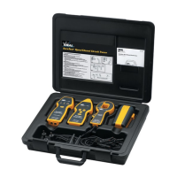
The tracers are available in three configurations: #61-954, #61-956, and #61-958. Each kit includes the same TR-958 transmitter and TL-958 test lead kit. The #61-954 kit features an RC-954 receiver with a 7-digit LED screen and a C-954 hard case. The #61-956 kit upgrades to an RC-958 receiver with a rotating, super-bright OLED display and an AC/DC power indicator, along with the C-954 hard case. The high-end #61-958 kit includes the RC-958 receiver, an IC-958 inductive clamp with a BP-958 battery pack, and a larger C-958 hard case.

Key Features:

  • Numeric Value and Variable Audible: Provides easy-to-understand tracing with a numeric value and a variable pitch/tone that increase as the signal strengthens.
  • Super-Bright Display: Ensures easy viewing of readings in various lighting conditions.
  • Peak Detecting Bar Graph: Offers instantaneous changes in signal strength for precise identification.
  • Breaker and Fuse Identification: Accurately identifies circuit breakers and fuses.
  • Open and Short Pinpointing: Locates opens and shorts in circuits.
  • Wire Tracing: Traces wires behind walls and underground.
  • Versatile Operation: Can be used on de-energized/energized circuits from 0-600V AC/DC.
  • GFCI Compatibility: Will not affect GFCIs or other sensitive equipment on the line.
  • Low Battery Indicator: Alerts users when batteries need replacement.
  • Safety Rating: Cat III-1000V safety rating.

Transmitter (TR-958) Features:

  • Input Jacks: Non-polarized, standard banana plug type.
  • Power Indicator: An LED illuminates when the transmitter is On, indicating signal production.
  • Line Energized Indicator: An LED illuminates if voltage greater than 30V AC/DC is present across input terminals, communicating line voltage status to the receiver.
  • Low Battery Indicator: Flashes when batteries reach 10% discharge, then becomes steady-on when fully exhausted.
  • Power Button: Switches power on/off and enables/disables transmit function to conserve battery.
  • Operating Range: 0 to 600V AC/DC on energized/de-energized circuits.
  • Battery Compartment: Holds (4) AA batteries for maximum transmit power and battery life.
  • Safety: Rated for Cat III-1000V environments with a high-energy, fast-acting fuse.
  • Signal Characteristics: Produces a 32 kilohertz, fixed-amplitude, time-modulated signal that does not affect sensitive electronic equipment. In closed circuits, the small load current allows signal detection upstream through feeder panels and distribution transformers, with signal strength reduced inversely to the transformer's turns ratio. Compatible with GFCI protected circuits.

Receiver (RC-954/RC-958) Features:

  • Super Bright Display: RC-954 has a 7-digit LED display; RC-958 has a rotating, super-bright OLED display.
  • Battery Power Button: Displays remaining battery life.
  • Audible Indication: Turns sound on/off; when on, produces a variable pitch/tone proportional to signal strength.
  • Sensitivity Mode Button: Selects sensitivity modes:
    • Search High ("1" / "SH"): Highest sensitivity (default mode), ideal for tracing in closed circuits with 120VAC plug adapter, open circuits, underground, or when more signal detection is needed.
    • Search Low ("2" / "SL"): High-medium sensitivity, used to reduce sensitivity if Search High mode has signal saturation.
    • Trace ("3" / "TR"): Medium-low sensitivity, used for tracing in closed circuits with the 25' lead and remote return path, or when Search Low mode has signal saturation.
    • Breaker ("4" / "BR"): Lowest sensitivity, used for identifying circuit breakers/fuses, pinpointing individual wires in a bundle, or when Trace mode has signal saturation.
  • Power Button: Switches power on/off to conserve battery.
  • Battery Compartment: Holds (3) AA batteries.
  • Safety: Rated for Cat III-1000V environments.
  • Receiver Orientation: Signal intensity depends on receiver orientation. Rotating the receiver to find the strongest signal (highest reading) is crucial for accurate tracing, especially when wires change direction. The back of the receiver is used for sweeping walls/floors to determine general location, while the nose pinpoints specific locations. Steel and aluminum conduits attenuate signals, requiring higher sensitivity or closer placement.

Test Lead Kit (TL-958):

  • TLOP-958 Outlet Plug Adapter: For plugging into standard 120VAC outlets.
  • TLBP-958 (2) Blade Prongs: For inserting into a separate outlet with a remote neutral conductor as a return path.
  • TLGP-958 Ground Prong: For inserting into a separate outlet with a remote ground conductor as a return path.
  • TLAC-958 (2) Alligator Clips: For connecting directly to bare wires and grounding points.
  • TLA1-958 (2) 3' Lead Adapters: For use with clips and prongs to connect to bare wires and grounding points.
  • TLA2-958 25' Lead Adapter: For use with clips and prongs to connect to remote return paths.

Inductive Clamp (IC-958) with Battery Pack (BP-958) Features:

  • 1" (25mm) Jaw Opening.
  • Powerful Magnet: Induces a low voltage signal onto a closed circuit.
  • 6' Cord: Attaches to the battery pack for power.
  • Protective Case.
  • (8) C-cell Batteries.
  • Input Jack: For clamp cord.
  • Hang Mount: For magnetic strap.
  • Magnetic Strap (not shown): Hooks onto the battery pack and attaches to metal cabinets, panels, electrical boxes. Velcro strap wraps around and hangs from non-magnetic objects.
  • Function: Powered by the battery pack, it generates its own specific, time-modulated signal and couples it onto energized or de-energized circuits via transformer action. The circuit must be closed where the clamp is applied to propagate a signal, with both ends closed for maximum signal production.
  • Applications: Identifying downstream loads from a breaker, tracing conduit, and tracing industrial control circuits.
  • Caution: The clamp has no indicators for energized circuits. Disconnect the battery pack when not in use.

Theory of Operation:

The tracer system comprises a transmitter and a receiver. The transmitter injects a unique 32 kHz, fixed-amplitude, time-modulated signal into the circuit, inducing an electromagnetic field. The receiver detects this signal, providing a numeric value and a variable pitch/tone that strengthen with signal intensity.

  • Open vs. Closed Circuits: A closed circuit allows current flow, producing a much stronger electromagnetic field, which is optimal for tracing. In an open circuit, no current flows, resulting in a weaker field.
  • Remote Return Path: To optimize the transmitted signal and avoid canceling effects from opposing magnetic fields (e.g., hot and neutral conductors), the conductor to be traced should be separated from the return conductor using a remote return path (e.g., the 25' test lead to a remote neutral or ground from another circuit or a water pipe). For breaker identification, the AC outlet adapter is sufficient as hot and neutral are already separated at the panel. If the resistance between the circuit neutral and remote return path is >100 Ω, a different return path should be selected.

Applications:

  • Pre-test Operation: Before use, test the receiver by holding it near the powered transmitter or inductive clamp. A "99" numeric indication and strong audible sound confirm proper operation.
  • Locating Circuit Breakers and Fuses:
    1. Connect transmitter to the circuit (energized or de-energized) and power on. Energized circuits produce stronger signals.
    2. Turn on receiver. If multiple panels exist, use Search Low (SL/2) mode to identify the panel with the strongest signal. If multiple panels show strong signals, reduce sensitivity to Trace (TR/3).
    3. Open panel cover, set receiver to Breaker (BR/4) mode, and position it on its side.
    4. Slide receiver nose down each breaker. The breaker with the highest numeric reading is correct. If multiple breakers have similar readings, tip the receiver at 45° angles; only the correct breaker will show a strong signal in all positions. Alternatively, remove the panel cover and place the nose on individual hot wires.
    5. When the correct breaker is tripped, the signal will drop significantly, and the LED on the transmitter will turn off.
  • Tracing Wires Behind Walls:
    1. Connect transmitter to the circuit and power on. For optimal tracing, leave the circuit energized. If de-energized, connect the transmitter to neutral and ground conductors.
    2. Turn on receiver to Search High (SH/1) mode.
    3. Sweep with the receiver's back to find the strongest signal behind the wall, ceiling, or floor. Reduce sensitivity if the signal is too strong; use a remote return path if too weak, then reduce sensitivity to Trace (TR/3).
    4. Follow the highest reading until the circuit's end is found.
  • Finding Opens:
    1. Connect transmitter to the open circuit and power on.
    2. Turn on receiver to Search High (SH/1) mode.
    3. Sweep with the receiver's back to find the strongest signal. Reduce sensitivity if too strong; connect one lead of the transmitter to the open conductor and the other to a remote return path if too weak.
    4. Follow the highest reading until the signal falls off, indicating the open's location. Reduce sensitivity and use the receiver's nose to pinpoint. If the open is not found, capacitive coupling may be occurring; ground adjacent conductors and minimize distance between transmitter connection and the open.
  • Finding Shorts:
    1. Connect transmitter to the shorted circuit (one lead to faulted conductor, other to ground; conduit can be ground if fault is metallic; ground adjacent conductors if possible) and power on.
    2. Turn on receiver to Search High (SH/1) mode.
    3. Sweep with the receiver's back to find the strongest signal. Reduce sensitivity if too strong; use a remote return path if too weak.
    4. Follow the highest reading until the signal weakens, indicating the fault location. Reduce sensitivity and use the receiver's nose to pinpoint the source.
  • Sorting Bundled Wires:
    1. Connect transmitter to the circuit (one test lead to known end of wire, other to remote return path) and power on.
    2. Turn on receiver to Breaker (BR/4) mode.
    3. Sort individual wires using the receiver's nose. Separate wires more if the signal is too strong; increase sensitivity to Trace (TR/3) if too weak.
    4. Continue sorting until the wire with the highest reading is identified.
  • Locating Cable, Conduit, or Metal Pipe Underground:
    1. Connect transmitter to the circuit and power on. Create a closed circuit by grounding the other end if possible. Ground adjacent conductors to eliminate capacitive-coupling. Use a remote return path to maximize signal.
    2. Turn on receiver to Search High (SH/1) mode.
    3. Sweep with the receiver's back to find the strongest signal underground. Reduce sensitivity if too strong; check ground connections (<100Ω) if too weak.
    4. Follow the highest reading until the circuit's end is found.
  • Inductive Clamp Applications (Alternative to Transmitter):
    • Identifying Downstream Loads from a Breaker:
      1. Remove panel cover, clamp around the hot wire of the energized (closed) circuit. Close the far end of the circuit (e.g., by plugging in a work light) to maximize signal.
      2. Hang battery pack on panel with magnetic strap.
      3. Plug clamp into battery pack.
      4. Set receiver to Search High (SH/1) mode and trace the circuit to the furthest outlet. Reduce sensitivity to Search Low (SL/2) if saturated.
    • Tracing Conduit:
      1. Clamp around the metallic conduit. Ground the far end of the conduit (e.g., using the 25' lead and alligator clips to the conduit end or electrical box, and a remote neutral/water pipe).
      2. Hang battery pack on panel/conduit with magnetic strap.
      3. Plug clamp into battery pack.
      4. Set receiver to Search High (SH/1) mode and trace the conduit. Reduce sensitivity to Search Low (SL/2) if saturated.
    • Tracing Industrial Control Circuits:
      1. Ensure the circuit is energized (closed at the panel). Close the other end (e.g., by turning on a motor/pump) to maximize signal.
      2. Clamp around the hot wire of the energized (closed) circuit.
      3. Use magnetic strap to hang battery pack on panel/motor control cabinet.
      4. Plug clamp into battery pack.
      5. Set receiver to Search High (SH/1) mode and trace the circuit to the other end. Reduce sensitivity to Search Low (SL/2) if saturated.

Maintenance:

  • Cleaning: Clean the case with a damp cloth and mild detergent. Do not use abrasives or solvents.
  • Service and Replacement Parts: The unit has no user-serviceable parts except for the fuse in the transmitter. For replacement parts or service inquiries, contact IDEAL Technical Support at 877-201-9005 or visit www.testersandmeters.com.

Battery and Fuse Replacement:

  • Transmitter (TR-958):
    1. Ensure test leads are removed from input jacks and the circuit.
    2. Remove battery cap by loosening the screw.
    3. Replace batteries with (4) new AA batteries.
    4. Assemble cap and re-tighten the screw.
    • Fuse Replacement (TR-958 only):
      1. Ensure test leads are removed.
      2. Remove (6) screws from the back of the transmitter.
      3. Replace fuse (#F-958).
      4. Re-assemble back cap and re-tighten screws.
  • Receiver (RC-954/RC-958):
    1. Remove battery cap by loosening the screw.
    2. Replace batteries with (3) new AA batteries.
    3. Assemble cap and re-tighten the screw.
  • Battery Pack for Inductive Clamp (BP-958):
    1. Ensure clamp is unplugged from battery pack.
    2. Remove cap by squeezing ribbed tabs.
    3. Remove battery holder, noting orientation to strap mount.
    4. Replace batteries with (8) new C-cell batteries.
    5. Re-install battery holder, noting orientation.
    6. Snap cap back onto case.

Specifications (TR-958 Transmitter):

  • Operating Frequency: 32 kilohertz, fixed-amplitude, time-modulated signal.
  • Current Output of Signal: 200mA p-pmax into 50 ohms.
  • Voltage Output of Signal: 30V nominal (2 watts).
  • Operating Voltage: 0 - 600V AC/DC.
  • Fuse: 1A/1000V, High-Energy, Fast-Acting (6mm x 46mm) - IDEAL #F-958.
  • Battery Power: 1.5V x (4) AA batteries (NEDA 15A, IEC LR6).
  • Battery Life: 40 hours open circuit testing / 25 hours short circuit tracing.
  • Indicators: On/Off, Line energized, Low battery.

Specifications (RC-954/RC-958 Receiver):

  • Sensing: Magnetic.
  • Maximum Range: 15 feet underground.
  • Signal Response: Numeric display and Audible beep.
  • Battery Power: 1.5V x (3) AA batteries (NEDA 15A, IEC LR6).
  • Battery Life: 20 hours.

Specifications (IC-958 Inductive Clamp with BP-958 Battery Pack):

  • Operating Frequency: 32 kilohertz, fixed-amplitude, time-modulated signal.
  • Current Output of Signal: 200mA p-pmax into 50 ohms.
  • Voltage Output of Signal: 30V nominal (2 watts).
  • Operating Voltage: 0 - 600V AC/DC.
  • Battery Power: 1.5V x (8) C-cell batteries (NEDA 14A, IEC LR14).
  • Battery Life: 15 hours.

Specifications (Circuit Tracer Kits):

  • Operating Temperature: 32°F (0°C) to 122°F (50°C).
  • Storage Temperature: -40°F (-4°C) to 154°F (90°C) (without batteries installed).
  • Humidity (Operating): 95% R.H. max.
  • Dimensions (W x H x D):
    • 61-954/956: 14.0 x 11.3 x 3.3 in. (355 x 285 x 83 mm).
    • 61-958: 18.5 x 14.6 x 3.5 in. (470 x 371 x 89 mm).
  • Weight:
    • 61-954/956: 4.5 lbs. (2.1 kg).
    • 61-958: 7.9 lbs. (3.6 kg).
  • Accessories Included: Receiver, Transmitter, test lead kit, hard case, batteries, instruction manual.
  • Safety: Complies with EN 61010-1, EN 61010-2-032, UL 61010-1, IEC 61010-2-032, IEC 61010-031 specifications, Cat III-1000V.
  • Other Regularity: FCC Part 15 compliant, FCC recognized device.
  • Compliances: Double Insulation. Instrument evaluated and complies with insulation category III (overvoltage category III). Pollution degree 2 in accordance with IEC-644. Indoor use.

Warranty Statement:

This tester is warranted to the original purchaser against defects in material and workmanship for the lifetime of the product. IDEAL INDUSTRIES, INC. will, at its option, replace or repair defective units. The warranty does not cover defects from abuse, neglect, accident, unauthorized repair, alteration, or unreasonable use. Implied warranties are limited to the above. The manufacturer is not liable for loss of use or incidental/consequential damages. State laws vary regarding these limitations.

IDEAL 61-954 Specifications

General IconGeneral
BrandIDEAL
Model61-954
CategoryMeasuring Instruments
LanguageEnglish

Related product manuals