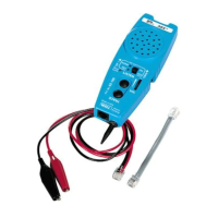
The IDEAL ABS™ Tester (Almost a Butt Set) is a simple to use tester for basic trou-
bleshooting of analog voice system installations. It monitors phone lines for dial tone
quality and presence of power, tests for correct jack polarity (detects reversed tip and
ring), and indicates call addressing for correct telephone extensions.
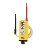
ABS™ Tester
• Simple to use for basic troubleshooting of communication systems.
• Used for diagnostic work involved with analog voice system installation and
maintenance.
• Will receive and reproduce telephone system dial tone for the purpose of determining the quality of the
tone. (LISTEN function or OFF hook)
• Checks tip and ring jack polarity.
• Identifies presence of power. (AC and DC)
• Indicates call addressing for correct telephone extensions.
• Equipped for jack and cross-connect system access.
• Receives tracing signals for identifying specific conductors in a cable run. (TRACE function requires separate tone.
• Volume control to adjust test tones.
• Clip lead access for two center pins of RJ11 jack.
• 60 cycle noise rejection for clear tone detection
• Lanyard attachment point for hands free operation
• Drop resistant, moisture resistant case and speaker for long life durability.
• Replaceable line cord assembly to maximize life of tester
• Comes complete with 9 volt battery installed in tester
• Pocket sized
WARNING
If OVERLOAD LED (Red) is illuminated and warning tone sounds, the telephone line being tested is a digital line. Toggle off the LISTEN button or remove the tester
from the line within 30 seconds to avoid damage to the tester.
Instructions for Use
To Monitor for Dial Tone Quality at a Modular Jack
1. Plug the ABS™ Tester into a phone system jack using a jumper cable (supplied with ABS™ Tester).
2. Turn Line Status switch to ON position.
3. The Line Status LEDs will show if the line under test has DC power and if it is wired correctly with a Green NORM LED
4. Push the LISTEN button, taking the line “off” hook and hear the dial tone.
5. Listen for good clean dial tone.
6. Push LISTEN again to end test.
(Note: The LISTEN feature can be toggled on and left on without draining the battery. Some digital systems can be listened to d
epending on the digital system being
tested.)
To Monitor Dial Tone at a Cross Connect
1. Plug modular plug on clip jumper (supplied with ABS™Tester) into ABS™ Tester jack.
2. Use clips to connect to appropriate contacts on cross connect terminals.
3. Push the LISTEN button, taking the line “off” hook and hear the dial tone.
4. Listen for good clean dial tone.
5. Push LISTEN again to end test.
(Note: The LISTEN feature can be toggled on and left on without draining the battery. Some digital systems can be listened to d
epending on the digital system being
tested.)
To Detect Tracing Tone Signal
1. Push TRACE button and the probe end becomes active.
2. Hold TRACE to trace a line within a bundle of cables or to “tone out” a line on a punch down block.
To Detect Tracing Tone Signal at Wall Outlet
1. Plug the ABS™ into a wall outlet using a jumper cable (supplied with ABS™).
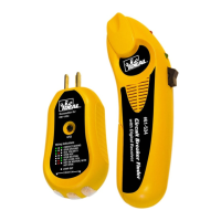
2. Push TRACE to hear tone if the line to that wall outlet has been activated with a signal from another source such as IDEAL AB
S™ Signal Thrower™ #62-184 or
IDEAL PathFinder™ #62-080.
Test for Line Status
1. Plug the ABS™ Tester into a wall outlet using a jumper cable.
Test Results:
• Green NORM lights when the communication line under test is powered up and the TIP pin/wire is positive with respect to the RING pin/wire and the phone is “on-
hook”.
• Red REV indicator will light if TIP an RING polarity are reversed.
• Both NORM and REV LEDs will be illuminated if an AC voltage is present.
• Both NORM and REV LEDs will flash if the line is ringing (for phone number verification).
Clip Lead Access
1. Attach alligator clips from butt set, tone generator, or other test equipment to large perforated test pads allow secure for access to the two center pins of an RJ11
jack.
2. The LINE STATUS switch can be in ON or OFF position when using test pads.
Note: In the OFF position a 10K load is removed from the test terminal to the RJ11 interface circuit.
Accessory Part
K-8343 Cable Assembly, RJ11/Alligator clips
K-7919 RJ11/RJ11 Cable Assembly
Battery Replacement
1. Remove screws from back of case using a #1 Phillips screwdriver. Carefully open tester.
2. Remove old battery.
3. Install new battery (9 volt battery).
4. Close tester and replace screws. Do not over tighten.
Warranty limited solely to repair or replacement; no warranty of merchantability, fitness for a particular purpose or consequential damages.
IDEAL INDUSTRIES, INC.
Sycamore, IL 60178, U.S.A.
800-304-3578 Customer Assistance
800-947-3614 DataComm Assistance
www.idealindustries.com
ND 1000-4
Made in U.S.A.
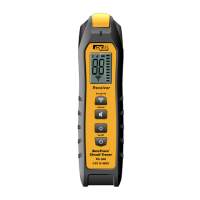
ABS™ Tester Instruction Sheet
#62-180
Volume Control
Checks tip and
ring polarity
Lanyard attachment
Drop-resistant,
moisture-resistant
durable case
Listen to monitor dial
tone quality
Probe receives tracing
signals
El probador ABS™ de IDEAL (casi como un aparato telefónico para técnicos de
reparación) es un probador fácil de usar para la localización y reparación básicas de
fallas de instalaciones de sistemas de voz analógicos. Monitorea la calidad del tono
de marcado y la presencia de corriente en las líneas telefónicas, prueba si la polari-
dad de los jacks es correcta (detecta la inversión de la punta y el anillo), e indica
direcciones de llamadas para extensiones de teléfono correctas.
Probador ABS™
• Es sencillo de usar para localizar y reparar fallas de sistemas de comunicaciones.
• Se usa para efectuar trabajos de diagnóstico en los que se incluye la instalación y el mantenimiento
de sistemas de voz analógicos.
• Recibirá y reproducirá el tono de marcado del sistema telefónico para determinar la calidad del tono.
(Función ESCUCHAR o DESCOLGADO).
• Comprueba la polaridad del jack (punta y anillo).
• Identifica la presencia de corriente (CA y CC).
• Indica direcciones de llamadas para extensiones de teléfono correctas.
• Equipado para el acceso de jacks y sistemas de transconexión.
• Control de volumen para ajustar los tonos de prueba.
• Acceso de cables de pinzas para dos clavijas centrales del jack RJ11.
• Acción antirruido de 60 ciclos para la detección clara de tonos.
• Punto de sujetador de cordón que permite tener las manos libres.
• Caja y altavoz resistentes a las caídas y a la humedad que prolongan la duración.
• Conjunto de cordón de línea reemplazable para aumentar al máximo la duración del probador.
• Viene completo con pila de 9 voltios instalada en el probador.
• Tamaño bolsillo.
ADVERTENCIA
Si se enciende el LED OVERLOAD (sobrecarga) y suena el tono de advertencia, significa que la línea telefónica que se está probando es una línea digital. Ponga el
interruptor LISTEN en la posición de apagado o desconecte el probador de la línea en un plazo máximo de 30 segundos para impedir que se dañe el probador.
Instrucciones de uso
Para monitorear la calidad del tono de marcado en un jack modular
1. Enchufe el ABS™ en un jack del sistema telefónico usando un cable puente (suministrado con ABS™).
2. Ponga el interruptor de estado de la línea en la posición de encendido.
3. Los LED de estado de la línea mostrarán si la línea que se está probando tiene corriente continua y si está bien conectada co
n un LED NORM de color verde.
4. Pulse el botón LISTEN, “descolgando” la línea y escuche si hay un tono de marcado.
5. Escuche si se produce un tono de marcado claro.
6. Pulse LISTEN nuevamente para terminar la prueba.
(Nota: La función LISTEN puede pasarse a la posición de encendido y dejarse en esa posición sin drenar la pila. Ciertos sistema
s digitales pueden escucharse depen-
diendo del sistema digital que se esté probando).
Para monitorear el tono de marcado en una transconexión
1. Conecte el enchufe modular en el puente de pinza (incluido con ABS™) sdentro del jack ABS™.
2. Use pinzas para conectar los contactos apropiados en los terminales de transconexión.
3. Pulse el botón LISTEN, “descolgando” la línea y escuche el tono de marcado.
Hoja de instrucciones del probador ABS™
#62-180
Control de volumen
Comprueba la
polaridad de la
punta y el anillo
Sujetador de cordón
Caja duradera
resistente a las caídas
y a la humedad
Permite escuchar para
monitorear la calidad del
tono de marcado
La sonda recibe señales
de rastreo