EasyManua.ls Logo

IDEAL Vol-Con 61-076 User Manual

IDEAL Vol-Con 61-076
11 pages
To Next Page IconTo Next Page
Page #1 background imageLoading...
Page #1 background image
Vol-Con
®
Voltage/
Continuity Tester (61-076)
Vol-Test™ Voltage Tester
(61-065)
Instruction Manual
WARNING
Read First: Safety Information
Use the tester only as specified in this manual;
otherwise, the protection provided by the tester
may be impaired.
Warning
To avoid possible electric shock or personal
injury, follow these instructions:
Do not use tester if it is damaged. Visually
inspect tester to ensure case is not cracked.
Inspect and replace leads if insulation is dam-
aged, metal is exposed, or probes are cracked.
Do not use tester if it operates abnormally as
protection maybe impaired.
Do not use during electrical storms or in wet
weather.
Do not use around explosive gas, dust, or
vapor.
Do not apply more than the rated voltage to
the tester.
Always operate this solenoid-type tester
within the specified duty cycle on the front of
the tester.
Do not use without batteries and caps
properly installed. (61-076)
Remove test leads prior to removing battery
caps. (61-076)
Caution
To protect yourself, think "Safety First":
Voltages exceeding 30VAC or 60VDC pose a
shock hazard so use caution.
Never ground yourself when taking electrical
measurements.
Use appropriate personal protective equip-
ment such as safety glasses, face shields,
insulating gloves, insulating boots, and/or
insulating mats.
Before each use:
Perform a continuity test by touching the
probe tips together, the continuity LED
should light. This test verifies the func-
tionality of the batteries and test leads.
(61-076)
Verify tester operation by measuring a
known voltage. Apply tester to circuit under
test. And, then test on the known live volt-
age again to ensure proper operation.
Connect the black common lead to
ground before applying the red test lead
to voltage. Disconnect the red test lead
from the voltage first.
Always work with a partner.
When using the probes, keep fingers as far
behind the probe tips as possible.
Features:
Vibration Mode with indicator movement
Auto-Switching Voltage/Continuity
Technology (61-076)
Independent solenoid and electronic circuitry
design provides back-up voltage indication
for added safety
Low Impedance
Replaceable Test Leads
Shielded probe tips
Ultrasonically welded and o-ring sealed for
added durability
Indicates:
• 100-600V AC/DC (61-065)
5-600V AC/DC (61-076)
#61-076
#61-065
2
ND 3522-5 Vol-Con Instruct 3/25/08 4:04 PM Page 1

Other manuals for IDEAL Vol-Con 61-076

Question and Answer IconNeed help?

Do you have a question about the IDEAL Vol-Con 61-076 and is the answer not in the manual?

IDEAL Vol-Con 61-076 Specifications

General IconGeneral
BrandIDEAL
ModelVol-Con 61-076
CategoryTest Equipment
LanguageEnglish

Summary

Safety Information and Warnings

General Safety Precautions

To avoid possible electric shock or personal injury, follow specific safety instructions and guidelines.

Cautions for Safe Operation

Voltages exceeding 30VAC or 60VDC require caution and appropriate PPE. Never ground yourself.

Tester Features

Key Capabilities

Includes vibration mode, auto-switching voltage/continuity, independent circuitry, low impedance, and replaceable leads.

Voltage and Continuity Indicators

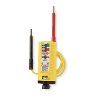
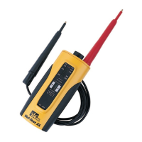
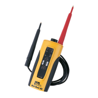
Indicates 100-600V AC/DC for model 61-065 and 5-600V AC/DC for model 61-076.

Operating Procedures

Measuring AC/DC Voltage

Connect tester in parallel with load/circuit to indicate voltage type, polarity, and level.

Testing for Continuity

Connect tester to de-energized circuit; continuity LED lights if resistance is <500kΩ.

Practical Applications

Locating Blown Fuses

Test fuses for continuity with power off; check voltage across fuses with power on.

Finding Grounded Line Side

Identify the grounded side of a line by finding a terminal with no voltage indication.

Checking Continuity of Devices

Test circuits, cords, and appliances for continuity by connecting tester across circuit.

Locating Excessive Leakage to Ground

Detect >5VAC (N-G) leakage by testing neutral to ground connection.

Maintenance, Support, and Warranty

Battery Replacement Procedure

Replace batteries when continuity LED no longer lights. Pry caps, replace, snap caps back.

Accessories and Maintenance

Lists available accessories and recommends cleaning the case with a damp cloth.

Service and Replacement Parts

Contact Technical Support for parts or service information via phone or website.

Warranty Statement

Two-year warranty against defects in material/workmanship; excludes abuse, neglect, etc.

Product Specifications

Technical Specifications

Details VAC/VDC ranges, accuracy, overload protection, environment, battery, dimensions, weight, and safety ratings.

Insulation and Usage Standards

Instrument complies with insulation category III, pollution degree 2, and is for indoor use.

Related product manuals