EasyManua.ls Logo

IDEAL Vol-Con XL

IDEAL Vol-Con XL
5 pages
To Next Page IconTo Next Page
Loading...
Vol-Con
®
XL (61-086)
Voltage/Continuity Tester
and Vol-Test™ (61-085)
Voltage Tester
Instruction Manual
WARNING
Read First: Safety Information
This tester complies with UL3111-1, Cat
III-600 overvoltage protection, Pollution
Degree 2. Use the tester only as specified
in this manual; otherwise, the protection
provided by the tester may be impaired.
In this manual, a Warning identifies con-
ditions and actions that pose hazards to the
user. A Caution identifies conditions and
actions that may damage the meter or the
equipment under test.
Warning
To avoid possible electric shock or person-
al injury, follow these guidelines:
Do not use tester if it is damaged.
Visually inspect tester to ensure case is
not cracked and battery cap is in place.
Inspect and replace leads if insulation is
damaged, metal is exposed, or probes are
cracked. Pay particular attention to the
insulation surrounding the connectors.
Do not use tester if it operates abnor-
mally as protection maybe impaired.
Do not use during electrical storms or
in wet weather.
Do not use around explosive gas, dust,
or vapor.
Do not apply more than the rated volt-
age to the tester. Voltage is not to
exceed 600V.
Always operate this solenoid-type tester
within the specified duty cycle on the
front of the tester. Duty cycle ratio is:
1:15 ON:OFF time.
Maximum ON time is 15 seconds.
Do not use without batteries and cap
properly installed.
Remove test leads prior to removing
battery cap.
Caution
To protect yourself, think "Safety First":
Voltages exceeding 30VAC or 60VDC
pose a shock hazard so use caution.
Never ground yourself when taking
electrical measurements.
Use appropriate personal protective
equipment such as safety glasses, face
shields, insulating gloves, insulating
boots, and/or insulating mats.
Use the 3-Step Testing Method. Before
each use:
Perform a continuity test by touching
the probe tips together, an audible
sound should be heard and the con-
tinuity LED should light. This test
verifies the functionality of the batter-
ies and test leads (61-086 only).
#61-085
#61-086
ND 3401-1 61-085/086 Vol-Con In 9/22/03 10:34 AM Page 1
Question and Answer IconNeed help?

Do you have a question about the IDEAL Vol-Con XL and is the answer not in the manual?

IDEAL Vol-Con XL Specifications

Electrical Specifications IconElectrical Specifications
VAC Ranges120V, 240V, 480V, 600V AC
VDC Ranges120V, 240V, 600V DC
Operating Frequency25-60 Hz
Input ImpedanceLow
Operating Environment IconOperating Environment
Operating Temperature Range32° F to 122° F (<70% humidity)
Storage Temperature Range-4° F to 140° F (<80% humidity)
Altitude2000m
Indoor UseYes
Power and Battery IconPower and Battery
Battery Type4 x 1.5V (LR44)
Battery Life200 hours typical
Weight and Dimensions IconWeight and Dimensions
Height6.0 inches
Width2.3 inches
Depth1.2 inches
Weight8.0 oz

Summary

Safety Information and Warnings

General Safety Guidelines

Follow guidelines to avoid electric shock, injury, or equipment damage. Use caution with voltages.

Pre-use Checks and Conditions

Inspect tester and leads for damage. Do not use in hazardous environments or if abnormal.

Product Features and Accessories

Key Product Features

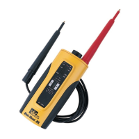
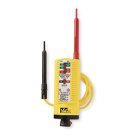
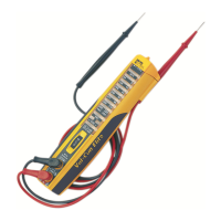
Details features like vibration mode, LED/audible indications, auto-switching, and durable design.

Included Accessories

Lists essential accessories like test leads and carrying case.

Measurement and Testing Procedures

AC Voltage Measurement Procedure

Connect leads properly and in parallel with the circuit to measure AC voltage type and level.

DC Voltage Measurement Procedure

Connect leads correctly and in parallel to measure DC voltage, polarity, and level.

Continuity Test Procedure

De-energize circuit, connect tester, and check for audible/LED indication below 500kΩ.

Practical Applications

Locating Blown Fuses

Use continuity check for fuses with power off, or voltage checks with power on.

Finding Grounded Side of Line

Identify the grounded line terminal by checking for no voltage indication.

Advanced Testing and Maintenance

Testing Grounded Side of MotorAppliance

Check for continuity to frame or no voltage indication on terminals to find grounded side.

Testing for 25 to 60 Cycle Frequency

Distinguish 25-60 Hz frequency by hum frequency and vibration speed.

Checking Continuity of CordsMotors

Verify continuity of cords, motors, and appliances by checking for audible beep.

Battery Replacement (61-086 only)

Instructions for replacing the four 1.5V batteries when needed.

Test Lead Replacement

Replace leads only with specified IDEAL test leads, noting fused probe tips.

Specifications and Warranty

Product Specifications

Details voltage ranges, accuracy, frequency, impedance, environment, and battery life.

Maintenance Guidelines

Clean the case with a damp cloth and mild detergent. Avoid abrasives or solvents.

Service and Replacement Parts

Contact IDEAL INDUSTRIES for replacement parts or service information.

Warranty Statement

Tester is warranted against defects for five years from purchase.

Related product manuals