EasyManua.ls Logo

IDEAL 61-520 - User Manual

IDEAL 61-520
2 pages
Print Icon
To Next Page IconTo Next Page
Loading...
OPERATING
INSTRUCTIONS
PHASESEQUENCE
ANDOPENPHASE
INDICATOR
#61-520
HOW TO CHECK PHASE SEQUENCE (cont’d)
Fig. 3
IDEAL INDUSTRIES,INC.
Sycamore,IL60178,U.S.A.
800-435-0705CustomerAssistance
www.idealindustries.com
ND-1714-2
PLEASEREAD
CAREFULLY
Misuse and abuse of
these instructions can-
not be prevented by any
printed word and may
cause injury and or
equipment damage.
Please follow these
instructions faithfully and
adhere to all standard
industry safety rules.
ShownApprox.
1/3ActualSize
WARRANTYSTATEMENT
Thistesteriswarrantedtotheoriginalpurchaseragainstdefectsin
materialand workmanshipfortwo yearsfromthe dateofpurchase.
During this warranty period, IDEAL INDUSTRIES, INC. will, at its
option,replace or repair the defective unit, subject toverification of
thedefectormaltifunction.Thiswarrantydoesnotcoverfuses,bat-
teriesordamagefromabouse,neglect,accident,unauthorizedrepair,
alteration,orunreasonableuseoftheinstrument.
Anyimpliedwarranties arising out of the saleofanIDEALproduct,
includingbut limited toimpliedwarranties of merchantebilityandfit-
nessforaparticularpurpose,arelimitedtotheavobe.Themanufac-
turershallnotbeliableforlossofuseoftheinstrumentorotherinci-
dentalorconsequentialdamages,expenses,oreconomicloss,orfor
anyclaimorclaimsforsuchdamage,expensesoreconomicloss.
Statelawsvary,sotheabovelimitationsorexclusionsmaynotapply
toyou.Thiswarrantygivesyouspecificlegalright,andyoumayalso
haveotherrightswhichvaryfromstatetostate.
IDEALINDUSTRIESINC.
Attention:RepairDept.
1000ParkAve.
Sycamore,IL60178
1
Thewarrantyisnotapplicableiftheinstrumenthasbeenmisused,
abused,subjectedtoloadsinexcessofspecifications,hashadunau-
thorizedrepairorhasbeenimproperlyassembledorused.
6. If the rotation of the disc is
COUNTER-CLOCKWISE
,release
'ON' button and transpose (interchange)the connections of any
two clips to the lines.
7.
Press the 'ON' button again, making certain that all 3 lamps are lit
(no open phases), and check direction of the rotating disc, which
will be
CLOCKWISE .
Release 'ON' button at end of test.
5. If all 3 lamps are lit, check the direction of the
rotating disc on the front panel. If it is in a
CLOCKWISE direction , the Phase Se-
quence is R, S, and T, in order of the lines
where the Red, White and Blue clips are con-
nected.
Release the
'ON' button at conclusion of test.
Question and Answer IconNeed help?

Do you have a question about the IDEAL 61-520 and is the answer not in the manual?

Summary

Warranty Statement

Front Panel View

Importance of Phase Sequence Indication

Specifications

Packaging

How to Check Phase Sequence

Step 5: Clockwise Rotation

Check rotating disc direction; CLOCKWISE indicates R, S, T sequence.

Step 6: Counter-Clockwise Rotation

If disc is COUNTER-CLOCKWISE, transpose two clips and re-test.

Step 7: Final Check

Press ON button again. CLOCKWISE rotation confirms correct sequence.

Overview

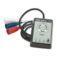
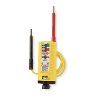
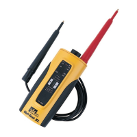
The device is the IDEAL Model 61-520, a Phase Sequence and Open Phase Indicator. It is a positive action electrical tester designed to instantly and accurately indicate both phase sequence and phase continuity in 3-phase power systems.

Function Description:

The primary function of the IDEAL Model 61-520 is to determine the order in which phase voltages appear on a system (Phase Sequence) and to detect if any of the phases are open (Open Phase). This is crucial during repairs, maintenance, or when paralleling 3-phase transformers or banks, as a reversed phase sequence can cause 3-phase motors to run in reverse. Such an occurrence can lead to severe personal injury, property damage, and equipment damage, especially in applications involving rotating machinery like woodworking, metalworking, escalators, elevators, and automation. The device helps ensure that all 3-phase components operate in the correct rotational direction.

Important Technical Specifications:

  • Voltage Range: Operates on 3-Phase Power Sources from 60V to 600V.
  • Duty Cycle: Continuous operation up to 500V. For voltages between 500V and 600V, the maximum continuous operation time is 5 minutes.
  • Frequency: Compatible with 50/60Hz systems.
  • Insulation Test: Withstands an AC voltage of 2,200V for 1 minute, ensuring robust electrical isolation.
  • Dimensions: The unit measures 4.24 inches (L) x 3 inches (W) x 1.6 inches (D) (106mm x 75mm x 40mm), making it compact and portable.
  • Weight: Approximately 12.5 ounces (350g).
  • Line Cord: Features a 60-inch long line cord with three alligator clips (Red, White, Blue) for easy connection to the power source.

Usage Features:

The device features a front panel with several indicators and controls:

  • Phase Sequence Indication Window: This window displays a rotating disc. The direction of rotation indicates the phase sequence.
  • Rotating Disc: A visual indicator that rotates to show the phase sequence.
  • "Open Phase" Check Lamps: Three lamps (R, S, T) at the bottom of the front panel indicate the status of each phase. The Red insulator clip is connected to the 'R' lamp, White to 'S', and Blue to 'T'. All three lamps must be lit for the phase sequence indicator to operate, signifying no open phases.
  • Push Button Switch ("ON" button): Located in the lower right corner of the front panel, this button must be pressed and held throughout the test.
  • Alligator Clips: Three color-coded clips (Red, White, Blue) are provided for connecting to the 3-phase power source. The connection positions are optional.

Operating Procedure:

  1. Connect the Red, White, and Blue alligator clips to the 3-phase power source. The order of connection to the lines does not matter initially.
  2. Press and hold the "ON" button on the front panel.
  3. Observe the "Open Phase" Check Lamps.
    • If all three lamps are lit, it indicates NO OPEN PHASES, and the phase sequence can then be checked.
    • If any lamp is NOT lit, it signifies an open phase. The Phase Sequence Indicator will not operate. The user must identify and correct the cause of the open phase before proceeding.
  4. Once all three lamps are lit, observe the rotating disc in the Phase Sequence Indication Window.
    • If the disc rotates in a CLOCKWISE direction, the phase sequence is R, S, T, corresponding to the lines where the Red, White, and Blue clips are connected.
    • If the disc rotates in a COUNTER-CLOCKWISE direction, the phase sequence is reversed. In this case, the user must release the "ON" button and transpose (interchange) the connections of any two clips to the lines.
  5. After transposing clips (if necessary), press the "ON" button again, ensuring all three lamps are lit, and re-check the direction of the rotating disc. It should now rotate CLOCKWISE.
  6. Release the "ON" button upon completion of the test.

Maintenance Features:

The device is designed for durability and comes with a warranty.

  • Warranty: The tester is warranted to the original purchaser against defects in material and workmanship for two years from the date of purchase. IDEAL INDUSTRIES, INC. will, at its option, replace or repair the defective unit, subject to verification of the defect or malfunction.
  • Warranty Exclusions: The warranty does not cover fuses, batteries, or damage resulting from abuse, neglect, accident, unauthorized repair, alteration, or unreasonable use of the instrument. It also does not apply if the instrument has been misused, abused, subjected to loads in excess of specifications, had unauthorized repair, or has been improperly assembled or used.
  • Repair Service: For warranty claims or repairs, users can contact IDEAL INDUSTRIES INC., Attention: Repair Dept., at 1000 Park Ave., Sycamore, IL 60178, or call Customer Assistance at 800-435-0705.
  • Packaging: The unit is packed in a handy unit box, complete with a pouch, operating instructions (Form ND-1714), and a warranty card, making it ready for immediate use and easy storage.

The device emphasizes safety by requiring adherence to all standard industry safety rules and warns against misuse and abuse of instructions, which could lead to injury or equipment damage.

IDEAL 61-520 Specifications

General IconGeneral
BrandIDEAL
Model61-520
CategoryTest Equipment
LanguageEnglish

Related product manuals