Do you have a question about the IDEAL 61-521 and is the answer not in the manual?
Procedure for replacing the meter's battery when the green lamp is dull lit.
Procedure for replacing the meter's fuse when indicated by connection issues.
Guidelines for cleaning the meter case with a damp cloth and storing it properly.
The IDEAL #61-521 is a versatile 3-Phase Tester and Motor Rotation Tester, designed to provide comprehensive diagnostic capabilities for electrical systems. This robust device combines three essential functions into a single, portable unit: open phase detection, phase sequence indication, and motor rotation indication. Its integrated design makes it an ideal tool for professionals involved in installing and maintaining conveyor lines, pump systems, and various interconnected drivers, ensuring efficient and safe operation of three-phase electrical machinery.
The primary function of the IDEAL #61-521 is to accurately identify the presence of an open phase, determine the correct phase sequence, and indicate the rotation direction of a motor. These capabilities are crucial for preventing damage to equipment, ensuring proper system performance, and maintaining safety in industrial and commercial electrical environments.
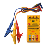
For 3-Phase Rotation Testing, the device is equipped with three input terminals labeled R, S, and T, corresponding to the red, yellow, and blue phases. When connected to a three-phase power source, the tester first verifies the integrity of all three phases. Three indicator lamps, one for each phase (R, S, T), illuminate if all phases are present and healthy. If any of these lamps fail to light up, it signifies an open phase condition on the corresponding terminal where the alligator clip is connected. This immediate feedback allows technicians to quickly identify and address power supply issues. Following the open phase check, the device indicates the phase sequence. If the clockwise indicator is lit, and the power source terminals are connected by the red, yellow, and blue alligator clips, the phase sequence indicators (R, S, and T) will also be lit, confirming a correct clockwise sequence. If the counter-clockwise indicator is lit, it means the phase connection is reversed, and the user should alternate the connection of two of the three alligator clips to achieve the desired clockwise rotation. This feature is vital for ensuring that three-phase motors and other sensitive equipment operate in the intended direction, preventing potential damage or malfunction.
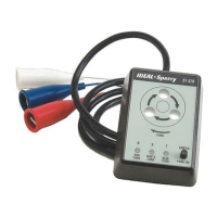
The Motor Rotation Tester function is designed to determine the rotational direction of a three-phase motor without applying live voltage, enhancing safety during installation and troubleshooting. This function uses separate input terminals labeled L1, L2, and L3. Before initiating a test, it is imperative to ensure that no voltage is present at the motor input terminals. Once the test leads are connected to the motor input terminals (L1-L2-L3), the user presses the power button on the tester. A green power indicator lamp will illuminate, confirming the tester is active. A critical safety check is integrated: if the clockwise or counter-clockwise red indicator lights up before the motor shaft is rotated, it signifies that voltage is still present at the motor terminals. In such a scenario, the user must immediately stop measuring, disconnect the test leads, and turn off the external power source to prevent electrical shock or damage. Once safety is confirmed, the user manually rotates the motor shaft clockwise. If the clockwise indicator on the tester illuminates, it confirms that the motor's internal wiring is configured for a three-phase connection to the power supply via L1-L2-L3, and the motor is intended to rotate clockwise. Conversely, if the user rotates the motor shaft counter-clockwise and the counter-clockwise indicator lights up, it means the motor is configured for counter-clockwise rotation with the L1-L2-L3 connection. If a specific rotation direction is required (e.g., counter-clockwise when the motor is configured for clockwise), the user would need to change the connection of the leads to L1-L2-L3 to achieve the desired rotational direction. This non-live testing capability significantly reduces the risk of electrical hazards during motor installation and maintenance.
The IDEAL #61-521 is designed for ease of use and safety, adhering to international electrical safety standards such as IEC Publication 348, IEC 1010 (En61010), and other relevant safety requirements.
Proper maintenance of the IDEAL #61-521 ensures its longevity and continued accurate performance. The manual provides clear instructions for battery and fuse replacement, as well as general cleaning.
The IDEAL #61-521 is a comprehensive and user-friendly tool, designed with safety and efficiency in mind, making it an indispensable asset for electrical professionals.
| Category | Test Equipment |
|---|---|
| Model | 61-521 |
| Manufacturer | IDEAL |
| Type | Digital Multimeter |
| Display | LCD |
| Continuity | Yes |
| Diode Test | Yes |
| Battery Required | Yes |
| Battery Type | 9V |
| AC Current Range | 200 µA to 10 A |
| DC Current Range | 200 µA to 10 A |
| Resistance Range | 200 Ω to 2 MΩ |
| AC Voltage Range | 200 mV to 600 V |
| DC Voltage Range | 200 mV to 600 V |