If additional elbows to those supplied in the
high level flue outlet kit are used, deduct
the following resistances (metres) from the
maximum boiler flue length.
57
1
/
2
˚
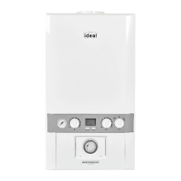
IMPORTANT
Flue must
always slope at
least 1
back to the
boiler
VERTICAL
HORIZONTAL
LEFT OR RIGHT 45˚ LEFT OR RIGHT
LOGIC (ALL MODELS) IDEAL PART NO.
High level flue outlet kit 208178
Logic Heat rear flue outlet (55/80) ONLY high level flue outlet kit (55/80) 205989
Flue extension kit 60 dia (1m) - for high level flue outlet kit 203228
High level 90° elbow 203229
High level 45° elbow 203230
LOGIC (ALL MODELS) METRES
90° elbow 1.4
45° elbow (pair) 1.25