Do you have a question about the IDEAL LOGIC COMBI ESP1 30 and is the answer not in the manual?
Crucial safety steps to take immediately if a gas leak is suspected.
Flowchart to diagnose and resolve common operational problems like no hot water or heating.
Action for low water pressure fault, including re-pressurisation steps.
Action for flame loss fault, checking gas supply and contacting engineer.
Action for fan fault, including restarting and contacting engineer if needed.
Action for flow thermistor fault, including restart and contacting engineer.
Action for return thermistor fault, including restart and contacting engineer.
Action for outside sensor failure, including restart and contacting engineer.
Action for low mains voltage fault, advising contact with electrician.
Action for unconfigured PCB fault, advising contact with engineer.
Action for overheat/no flow fault, checking pressure and contacting engineer.
Action for ignition lockout, checking condensate and gas supply.
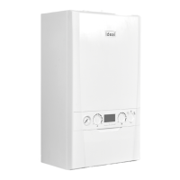
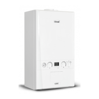
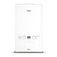
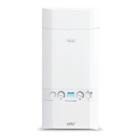
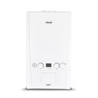
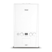
The Ideal Logic Combi ESP1 is a high-efficiency condensing combination boiler designed to provide both central heating and instantaneous domestic hot water. This appliance features full-sequence automatic ignition and fan-assisted combustion, ensuring reliable and efficient operation. Due to its high efficiency, the boiler produces condensate from the flue gases, which is drained to a suitable disposal point via a plastic waste pipe at the base of the unit. A condensate 'plume' may also be visible at the flue terminal during operation.
For your safety and to comply with regulations, this boiler must be installed by a Gas Safe Registered Engineer in the UK, or a Registered Gas Installer (RGII) in Ireland, in accordance with current regulations and electrical installation rules. It is crucial to follow the instructions in this booklet for safe and economical operation. The appliance must be earthed and requires a 230 V ~ 50 Hz electricity supply, with a 3A fuse. The casing must always be correctly fitted and sealed for proper operation. If installed in a compartment, it must not be used for storage. If a fault is suspected, the boiler must not be used until repaired by a qualified engineer. Under no circumstances should any sealed components be tampered with. This appliance can be used by children aged 8 and above, and persons with reduced physical, sensory, or mental capabilities, or lack of experience and knowledge, provided they receive supervision or instruction on safe use and understand the hazards. Children should not play with the appliance, and cleaning or user maintenance should not be performed by unsupervised children.
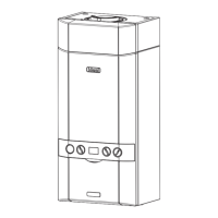
To start the boiler, ensure the electricity supply is off, set the mode knob to 'BOILER OFF', and both the Domestic Hot Water (DHW) and Central Heating (CH) temperature knobs to 'MAX'. Confirm all hot water taps are closed. Switch on the electricity and external controls (programmer, room thermostat). Finally, set the mode knob to 'Winter' (snowflake icon). The boiler will then initiate its ignition sequence and supply heat if required. The boiler status display shows codes like '00' for standby, a radiator icon for central heating, a tap icon for domestic hot water, and 'FP' for frost protection. The burner 'on' indicator illuminates when the burner is active. If the boiler fails to ignite after five attempts, fault code 'L2' will be displayed.
The domestic hot water temperature is adjustable via the DHW temperature knob (A), with a maximum of 65°C. Flow rates and temperature rise will vary, requiring tap adjustment: lower flow rates result in higher temperatures. The central heating radiator temperature is controlled by the CH temperature knob (B), with a maximum of 80°C. An economy setting 'e' is available for efficient heating.
The boiler automatically adjusts its output to match heat demand, reducing gas consumption. For optimal efficiency, turn the central heating temperature knob (B) to the 'e' position or lower. In colder periods, it may be necessary to increase this setting. Reducing the room thermostat by 1°C can save up to 10% on gas. If weather compensation is fitted, the CH temperature knob controls room temperature; adjust it to achieve the desired setting, and the system will automatically maintain it.
The boiler has built-in frost protection that operates in all modes, provided the power supply is on. If the boiler water temperature drops below 5°C, the boiler will activate to prevent freezing. This protection does not guarantee protection for other parts of the system. If a system frost thermostat is installed, the boiler must be in 'Winter' mode for system-wide frost protection. If no system frost protection is available and frost is likely during a short absence, leave heating controls or the programmer on at a reduced temperature. For longer periods, draining the entire system is recommended.
To restart the boiler after a fault code (see section 8), press the restart button (G). The boiler will repeat its ignition sequence. If it still fails to start, consult a Gas Safe Registered Engineer or RGII.
To completely remove power from the boiler, turn off the mains power switch.
The system pressure gauge indicates the central heating system pressure. If the pressure falls below 1-2 bar, it may indicate a water leak. The boiler will not operate if the pressure drops below 0.3 bar. To repressurize the system:
The appliance has a siphonic condensate trap system to reduce the risk of freezing. If the condensate pipe freezes, follow these instructions:
For normal cleaning, dust with a dry cloth. For stubborn marks, wipe with a damp cloth and finish with a dry cloth. DO NOT use abrasive cleaning materials. The appliance should be serviced at least once a year by a Gas Safe Registered Engineer or RGII.
The manual provides flowcharts for troubleshooting 'No Hot Water', 'No Central Heating', and 'No Hot Water or Central Heating' scenarios. These guides direct users to check mains power, mode knob settings, programmer settings, room thermostat, and fault codes. If '00' is displayed, contact Ideal Customer Services if under warranty, or a Gas Safe Registered Engineer/RGII if out of warranty.
The manual lists various fault codes with descriptions and actions:
For any queries, contact the Ideal Consumer Helpline at 01482 498660. To restart the boiler, press the RESTART button, and it will repeat the ignition sequence if there is a heat demand.
| Model | Logic Combi ESP1 30 |
|---|---|
| Category | Boiler |
| Boiler Type | Combi |
| Mounting | Wall Mounted |
| Fuel Type | Gas |
| Output | 30 kW |
| Domestic Hot Water Output | 30 kW |
| Efficiency | 94% |
| ErP Heating Efficiency Class | A |
| ErP Water Heating Efficiency Class | A |
| DHW Flow Rate | 12.4 l/min |
| Central Heating Flow Temperature Range | 30-80°C |
| Dimensions | 700 x 395 x 278 mm |
| Warranty | 7 years |





 Loading...